Vega VEGACAP 64 Operating Instructions Manual
Hide thumbs
Also See for VEGACAP 64:
- Operating instructions manual (40 pages) ,
- Operating instructions manual (36 pages) ,
- Operating instructions manual (36 pages)
Table of Contents
Advertisement
Quick Links
Advertisement
Table of Contents

Related Manuals for Vega VEGACAP 64


Summary of Contents for Vega VEGACAP 64
- Page 1 Operating Instructions VEGACAP 64 - Relay (DPDT) Document ID: 30012 Capacitive...
-
Page 2: Table Of Contents
Technical data ......27 Dimensions ....... 31 VEGACAP 64 • - Relay (DPDT) - Page 3 Instructions manuals for accessories and replacement parts Tip: To ensure reliable setup and operation of your VEGACAP 64, we offer accessories and replacement parts. The associated documents are: 30174 - Electronics module VEGACAP series 60 34296 - Protective cover 31088 - Flanges according to DIN-EN-ASME-JIS-GOST VEGACAP 64 •...
-
Page 4: About This Document
This symbol indicates special instructions for Ex applications. List The dot set in front indicates a list with no implied sequence. à Action This arrow indicates a single action. Sequence Numbers set in front indicate successive steps in a procedure. VEGACAP 64 • - Relay (DPDT) -
Page 5: For Your Safety
During work on and with the device the required personal protective equipment must always be worn. 2.2 Appropriate use VEGACAP 64 is a sensor for level detection. You can find detailed information on the application range in chapter "Product description". -
Page 6: Safety Label On The Instrument
2.6 CE conformity This device fulfills the legal requirements of the applicable EC guidelines. By attaching the CE mark, VEGA provides a confirmation of successful testing. You can find the CE conformity declaration in the download area of www.vega.com. -
Page 7: Product Description
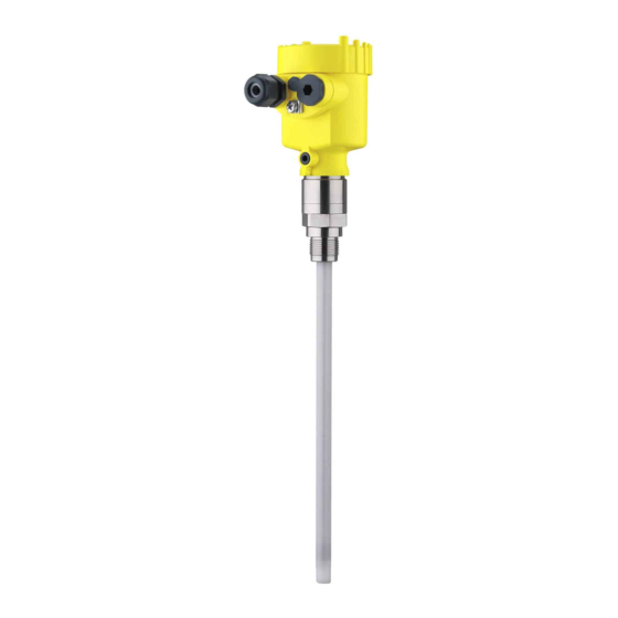
VEGACAP 64 consists of the following components: Components Housing cover Housing with electronics Process fitting with electrode Fig. 1: VEGACAP 64 - with plastic housing Housing cover Housing with electronics Process fitting active screen segment active probe Type label The type label contains the most important data for identification and... -
Page 8: Principle Of Operation
In addition to the type label outside, you can also find the serial number on the inside of the instrument. 3.2 Principle of operation VEGACAP 64 is a level switch with fully insulated, capacitive electrode Application area with active screen segment and active tip for level detection. -
Page 9: Operation
The capacitance change is converted by the electronics module into a switching command. VEGACAP 64 is a compact instrument, i.e. it can be operated without Power supply external evaluation system. The integrated electronics evaluates the level signal and outputs a switching signal. - Page 10 Not exposed to corrosive media Protected against solar radiation Avoiding mechanical shock and vibration Storage and transport Storage and transport temperature see chapter "Supplement - Technical data - Ambient conditions" temperature Relative humidity 20 … 85 % VEGACAP 64 • - Relay (DPDT)
-
Page 11: Mounting
Rain and condensation water can thus drain off. This applies mainly to outdoor mounting as well as installation in areas where high humidity is expected (e.g. through cleaning processes) or on cooled or heated vessels. Fig. 3: Measures against moisture penetration VEGACAP 64 • - Relay (DPDT) -
Page 12: Mounting Instructions
For this reason, do not use an overly long probe for VEGACAP 64, but check if you can mount a short level switch on the side of the vessel in horizontal position. Extreme vibration caused by the system, e.g. due to agitators or turbulence in the vessel from fluidisation, can cause the probe of... - Page 13 To compensate the normal voltage loss due to sealing materials, you flanges have to additionally use disc springs for fastening flange screws on PTFE coated flanges. Tighten the screws moderately with the torque stated in the technical data. VEGACAP 64 • - Relay (DPDT)
-
Page 14: Connect To Power Supply
Take note of the general installation regulations. As a rule, connect VEGACAP 64 to vessel ground (PA), or in case of plastic vessels, to the next ground potential. On the side of the housing there is a ground terminal between the cable entries. -
Page 15: Wiring Plan, Single Chamber Housing
Fig. 5: Connection steps 5 and 6 5.3 Wiring plan, single chamber housing Housing overview Fig. 6: Material versions, single chamber housing Plastic (not with dust-Ex) Aluminium Stainless steel Filter element for air pressure compensation VEGACAP 64 • - Relay (DPDT) - Page 16 DIL switch for mode adjustment Ground terminal Connection terminals Control lamp We recommend connecting VEGACAP 64 in such a way that the Wiring plan switching circuit is open when there is a level signal, line break or failure (safe condition).
- Page 17 5 Connect to power supply Fig. 8: Wiring plan Relay output Relay output Power supply VEGACAP 64 • - Relay (DPDT)
-
Page 18: Set Up
Note: As a rule, always set the mode with the mode switch (3) before starting setup VEGACAP 64. The switching output will change if you set the mode switch (3) afterwards. This could possibly trigger other connected instruments or devices. - Page 19 Screw the housing cover tightly up to the thread stop so that the inspection glass is above the control lamp (LED). To adjust VEGACAP 64, first of all remove the housing cover. Switching point adapta- You can adapt the switching point to the solid with the potentiometer.
- Page 20 (2) to the next higher measuring range. When the control lamp (6) lights green: continue with the next item. Turn the potentiometer (1) very slowly anticlockwise until the control lamp (6) lights red. VEGACAP 64 • - Relay (DPDT)
-
Page 21: Functional Chart
Dry run protection (6) (7) Relay energized Green Mode min. Dry run protection (6) (7) Relay deenergized Failure of the sup- ply voltage (min./max. mode) (6) (7) Relay deenergized Failure (6) (7) Relay deenergized flashes red VEGACAP 64 • - Relay (DPDT) -
Page 22: Maintenance And Fault Rectification
English language. The service is free of charge, only the standard telephone costs will be charged. VEGACAP 64 signals "covered" when the vibrating element is not Checking the switching signal submerged (overfill protection) -
Page 23: Exchange Of The Electronics Module
If you want to use an electronics module with a different signal output, you can download the corresponding operating instructions manual from our homepage under Downloads. Proceed as follows: Switch off power supply VEGACAP 64 • - Relay (DPDT) - Page 24 12 Press down the opening levers of the terminals, you will hear the terminal spring closing 13 Check the hold of the wires in the terminals by lightly pulling on them 14 Check cable gland on tightness. The seal ring must completely encircle the cable. VEGACAP 64 • - Relay (DPDT)
-
Page 25: Instrument Repair
If a repair is necessary, please proceed as follows: You can download a return form (23 KB) from our Internet homepage www.vega.com under: "Downloads - Forms and certificates - Repair form". By doing this you help us carry out the repair quickly and without having to call back for needed information. -
Page 26: Dismounting
Correct disposal avoids negative effects to persons and environment and ensures recycling of useful raw materials. Materials: see chapter "Technical data" If you have no possibility to dispose of the old instrument professionally, please contact us concerning return and disposal. VEGACAP 64 • - Relay (DPDT) -
Page 27: Supplement
60 Nm (44.25 lbf ft) Torque of the flange screws (min.) 100 Nm (74 lbf ft) Max. torque (process fitting - thread) 430 kHz Frequency Output variable Relay output (DPDT), 2 floating spdts Output VEGACAP 64 • - Relay (DPDT) - Page 28 Flange version ≥ 3"/DN 80, plated -0.4 … 64 bar/-40 … 6400 kPa (-5.8 … 928 psig), depending on the process fitting Process temperature VEGACAP 64 of 316L -50 … +150 °C (-58 … +302 °F) Process temperature (thread or flange tem- -50 …...
- Page 29 Max. detection or overflow protection DIL switch for measuring range selection range 1 0 … 20 pF range 2 0 … 85 pF range 3 0 … 450 pF Potentiometer Switching point adaptation Power supply Operating voltage VEGACAP 64 • - Relay (DPDT)
- Page 30 Depending on the version, instruments with approvals can have different technical data. For these instruments, the corresponding approval documents have to be taken into account. These are part of the delivery or can be downloaded under www.vega.com via "VEGA Tools" and "serial number search" as well as via "Downloads" and "Approvals".
-
Page 31: Dimensions
") ") ") M20x1,5/ M20x1,5/ M20x1,5/ M20x1,5 M20x1,5/ ½ NPT ½ NPT ½ NPT ½ NPT Fig. 30: Housing versions Plastic housing Stainless steel housing, electropolished Stainless steel housing - precision casting Aluminium housing VEGACAP 64 • - Relay (DPDT) - Page 32 9 Supplement A, G 1 A, G 1 ø16mm ( ") Fig. 31: VEGACAP 64 - threaded version G1 A (ISO 228 T1) = Sensor length, see chapter "Technical data" L1 = active length VEGACAP 64 • - Relay (DPDT)
- Page 33 9 Supplement ø 40 mm (1.58") Fig. 32: Temperature adapter VEGACAP 64 • - Relay (DPDT)
- Page 34 Les lignes de produits VEGA sont globalement protégées par des droits de propriété intellectuelle. Pour plus d'informations, on pourra se référer au site http://www.vega.com VEGA lineas de productos están protegidas por los derechos en el campo de la propiedad industrial. Para mayor información revise la pagina web http://www.vega.com Линии...
- Page 35 9 Supplement VEGACAP 64 • - Relay (DPDT)
- Page 36 All statements concerning scope of delivery, application, practical use and operating conditions of the sensors and processing systems correspond to the information avail- able at the time of printing. © VEGA Grieshaber KG, Schiltach/Germany 2009 30012-EN-090604 Subject to change without prior notice...
Need help?
Do you have a question about the VEGACAP 64 and is the answer not in the manual?
Questions and answers