Vega VEGACAP 63 Operating Instructions Manual
With transistor output
Hide thumbs
Also See for VEGACAP 63:
- Operating instructions manual (36 pages) ,
- Supplementary instructions manual (16 pages) ,
- Supplementary instructions manual (12 pages)
Table of Contents
Advertisement
Quick Links
Advertisement
Table of Contents

Related Manuals for Vega VEGACAP 63


Summary of Contents for Vega VEGACAP 63
- Page 1 Operating Instructions VEGACAP 63 with transistor output...
-
Page 2: Table Of Contents
Exchange of the electronics module ..Instrument repair ..... . . VEGACAP 63 - with transistor output... - Page 3 Dimensions ......Industrial property rights....VEGACAP 63 - with transistor output...
-
Page 4: About This Document
This symbol indicates special instructions for Ex applications. List The dot set in front indicates a list with no implied sequence. à Action This arrow indicates a single action. Sequence Numbers set in front indicate successive steps in a procedure. VEGACAP 63 - with transistor output... -
Page 5: For Your Safety
2.2 Appropriate use VEGACAP 63 is a sensor for level detection. Detailed information on the application range of VEGACAP 63 is available in chapter "Product description". 2.3 Warning about misuse Inappropriate or incorrect use of the instrument can give rise to application-specific hazards, e.g. -
Page 6: Safety Information For Ex Areas
2.7 Manufacturer declaration In conformity with DIN EN 60079-14/2004, para. 5.2.3, point c1, the capacitive probe VEGACAP 63 is suitable for use in zone 2. The operator must use the instrument correctly and follow the specifications of the following documents:... -
Page 7: Environmental Instructions
The environment man- agement system is certified acc. to DIN EN ISO 14001. Please help us fulfil this obligation by observing the environ- mental instructions in this manual: Chapter "Storage and transport" Chapter "Disposal" VEGACAP 63 - with transistor output... -
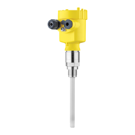
Page 8: Product Description
Housing cover Housing with electronics Process fitting 3.2 Principle of operation VEGACAP 63 is a level sensor with fully insulated capacitive Area of application electrode for level detection. VEGACAP 63 is very rugged and maintenance-free and can be used in all areas of industrial process technology. - Page 9 The capacitance change is converted by the oscillator into a switching command. VEGACAP 63 is a compact instrument, i.e. it can be operated Supply without external evaluation system. The integrated electronics evaluates the level signal and outputs a switching signal. With this switching signal, a connected device can be operated directly (e.g.
-
Page 10: Adjustment
PE foil is also used. Dispose of the packaging material via specialised recycling companies. Storage and transport temperature see "Supplement - Storage and transport tem- perature Technical data - Ambient conditions" Relative humidity 20 … 85 % VEGACAP 63 - with transistor output... -
Page 11: Mounting
Mounting 4 Mounting 4.1 General instructions In general, VEGACAP 63 can be mounted in any position. The Switching point instrument must be mounted in such a way that the probe is at the height of the requested switching point. With screwed versions, the housing must not be used for... -
Page 12: Mounting Information
Agitators and fluidization subjected to strong lateral forces. For this reason, do not use an overly long probe for VEGACAP 63, but check if you can mount a short level switch on the side of the vessel in horizontal position. - Page 13 Mounting The probe should protrude into the vessel to avoid buildup. For Socket that reason, avoid using mounting bosses for flanges and screwed fittings. This applies particularly to use with adhesive products. VEGACAP 63 - with transistor output...
-
Page 14: Connecting To Power Supply
Select power supply note of the general installation regulations. As a rule, connect VEGACAP 63 to vessel ground (PA), or in case of plastic vessels, to the next ground potential. On the side of the instrument housing there is a ground terminal between the cable entries. -
Page 15: Wiring Plans, Single Chamber Housing
5.3 Wiring plans, single chamber housing Housing overview Fig. 6: Material versions, single chamber housing Plastic (not with dust-Ex) Aluminium Stainless steel Filter element for pressure compensation or blind stopper with version IP 66/ IP 68, 1 bar VEGACAP 63 - with transistor output... - Page 16 DIL switch for mode adjustment Ground terminal Terminals Control lamp We recommend connecting VEGACAP 63 in such a way that Wiring plan the switching circuit is open when there is a level signal, line break or failure (safe condition). The instrument is used to control relays, contactors, magnet valves, warning lights, horns as well as PLC inputs.
- Page 17 Connecting to power supply Fig. 8: Wiring plan Fig. 9: NPN action Fig. 10: PNP action VEGACAP 63 - with transistor output...
-
Page 18: Wiring Plans, Version Ip 66/Ip 68, (1 Bar)
Connecting to power supply 5.4 Wiring plans, version IP 66/IP 68, (1 bar) Wire assignment, connection cable Fig. 11: Wire assignment, connection cable br (+) and bl (-) for power supply or to the processing system Screen VEGACAP 63 - with transistor output... -
Page 19: Set Up
Note: As a rule, always set the mode with the mode switch (3) before starting setup VEGACAP 63. The switching output will change if you set the mode switch (3) afterwards. This could possibly trigger other connected instruments or devices. - Page 20 Screw the housing cover tightly to the point where the inspection glass is above the control lamp (LED). To adjust VEGACAP 63, first of all remove the housing cover. You can adapt the switching point to the solid with the Switching point adaptation (1) potentiometer.
- Page 21 [lights red]. 12 Set the potentiometer (1) to the average value of the two noted values. The measuring system is now ready for operation. VEGACAP 63 - with transistor output...
- Page 22 (2) to the next higher stage and repeat the setting with the potentiometer (1) until the control lamp lights red. The measuring system is now ready for operation. VEGACAP 63 - with transistor output...
-
Page 23: Function Chart
Overfill protection min. mode transistor con- Dry run protection ducts Green min. mode transistor blocks Dry run protection Failure of the transistor blocks supply voltage (min./max. mode) Failure transistor blocks flashes red VEGACAP 63 - with transistor output... -
Page 24: Maintenance And Fault Rectification
Maintenance and fault rectification 7 Maintenance and fault rectification 7.1 Maintenance When used as directed in normal operation, VEGACAP 63 is completely maintenance-free. 7.2 Fault rectification VEGACAP 63 offers maximum reliability. Nevertheless faults Causes of malfunction can occur during operation. These may be caused by the following, e.g.:... -
Page 25: Exchange Of The Electronics Module
2 Unscrew the housing cover 3 Lift the opening levers of the terminals with a screwdriver 4 Pull the connection cables out of the terminals 5 Loosen the two screws with a Phillips screwdriver (size 1) VEGACAP 63 - with transistor output... - Page 26 13 Check the hold of the wires in the terminals by lightly pulling on them 14 Check the tightness of the cable entry. The seal ring must completely encircle the cable. 15 Screw the housing cover back on The electronics exchange is finished. VEGACAP 63 - with transistor output...
-
Page 27: Instrument Repair
Maintenance and fault rectification 7.4 Instrument repair If a repair is necessary, please proceed as follows: From our homepage in the Internet www.vega.com, you can download a return form (23 KB) under: “Downloads – Forms and Certificates – Repair form”... -
Page 28: Dismounting
Take note of chapters "Mounting" and "Connecting to power supply" and carry out the listed steps in reverse order. 8.2 Disposal VEGACAP 63 consists of materials which can be recycled by specialised recycling companies. We have purposely de- signed the electronic modules to be easily separable. -
Page 29: Supplement
55 V DC Blocking current <100 µA Modes (adjustable) min./max. Integration time - when immersed approx. 0.7 s - when laid bare approx. 0.7 s - in case of failure approx. 1 s VEGACAP 63 - with transistor output... - Page 30 -40 … +80°C (-40 … +176°F) Process conditions Process pressure -1 … 64 bar/-100 … 6400 kPa (-14.5 … 928 psi) Process temperature VEGACAP 63 of 316L - Insulation PE -40 … +80°C (-40 … +176°F) - insulation PTFE -50 … +150°C (-58 … +302°F) Process temperature (thread or flange...
- Page 31 Blue Adjustment elements Mode switch - min. min. detection or dry run protection - max. max. detection or overfill protection Depending on the version M12x1, acc. to DIN 43650, Harting, Amphenol- Tuchel, 7/8" FF VEGACAP 63 - with transistor output...
- Page 32 IP 66/IP 68 (1 bar) available Overvoltage category Protection class Approvals Overfill protection acc. to WHG Ship approvals Requirement to maintain the protection is the suitable cable. Deviating data with Ex applications: see separate safety instructions. VEGACAP 63 - with transistor output...
-
Page 33: Dimensions
Housing in protection IP 66/IP 68, 1 bar ~ 103mm ") ~ 150mm (5 ") ø 77mm ø 84mm (3 ") ") M20x1,5 M20x1,5 M20x1,5 Fig. 16: Housing versions in protection IP 66/IP 68, 1 bar Stainless steel housing Aluminium housing VEGACAP 63 - with transistor output... - Page 34 Supplement A, G 1 A, G 1 ø16mm ( ") Fig. 17: VEGACAP 63 - Threaded version G1 A = Sensor length, see "Technical data" ø 40mm (1 ") Fig. 18: Temperature adapter VEGACAP 63 - with transistor output...
- Page 35 Supplement VEGACAP 63 - with transistor output...
-
Page 36: Industrial Property Rights
Les lignes de produits VEGA sont globalement protégées par des droits de propriété intellectuelle. Pour plus d'informations, on pourra se référer au site http://www.vega.com. VEGA lineas de productos están protegidas por los derechos en el campo de la propiedad industrial. Para mayor información revise la pagina web http://www.vega.com. - Page 37 Supplement VEGACAP 63 - with transistor output...
- Page 38 Supplement VEGACAP 63 - with transistor output...
- Page 39 Supplement VEGACAP 63 - with transistor output...
- Page 40 All statements concerning scope of delivery, application, practical use and operating conditions of the sensors and processing systems correspond to the information avail- able at the time of printing. © VEGA Grieshaber KG, Schiltach/Germany 2006 Technical data subject to alterations 30010-EN-060222...
Need help?
Do you have a question about the VEGACAP 63 and is the answer not in the manual?
Questions and answers