Vega VEGACAP 64 Operating Instructions Manual
Capacitive rod electrode for level detection
Hide thumbs
Also See for VEGACAP 64:
- Operating instructions manual (36 pages) ,
- Operating instructions manual (36 pages) ,
- Operating instructions manual (36 pages)

Related Manuals for Vega VEGACAP 64


Summary of Contents for Vega VEGACAP 64
- Page 1 Operating Instructions Capacitive rod electrode for level detection VEGACAP 64 Transistor (NPN/PNP) Document ID: 30014...
-
Page 2: Table Of Contents
Exchange of the electronics module ................25 How to proceed if a repair is necessary ................27 Dismount Dismounting steps......................28 Disposal ......................... 28 Supplement Technical data ........................ 29 Dimensions ........................33 Industrial property rights ....................36 Trademark ........................36 VEGACAP 64 • Transistor (NPN/PNP) - Page 3 Instructions manuals for accessories and replacement parts Tip: To ensure reliable setup and operation of your VEGACAP 64, we offer accessories and replacement parts. The corresponding documenta- tions are: • 30174 - Electronics module VEGACAP series 60 • 34296 - Protective cover • 31088 - Flanges according to DIN-EN-ASME-JIS-GOST Editing status: 2017-04-06 VEGACAP 64 • Transistor (NPN/PNP)
-
Page 4: About This Document
Action This arrow indicates a single action. Sequence of actions Numbers set in front indicate successive steps in a procedure. Battery disposal This symbol indicates special information about the disposal of bat- teries and accumulators. VEGACAP 64 • Transistor (NPN/PNP) -
Page 5: For Your Safety
During work on and with the device the required personal protective equipment must always be worn. Appropriate use The VEGACAP 64 is a sensor for point level detection. You can find detailed information about the area of application in chapter "Product description". Operational reliability is ensured only if the instrument is properly used according to the specifications in the operating instructions manual as well as possible supplementary instructions. -
Page 6: Safety Label On The Instrument
That is why we have introduced an environment management system with the goal of continuously improving company environmental pro- tection. The environment management system is certified according to DIN EN ISO 14001. Please help us fulfil this obligation by observing the environmental instructions in this manual: • Chapter "Packaging, transport and storage" • Chapter "Disposal" VEGACAP 64 • Transistor (NPN/PNP) -
Page 7: Product Description
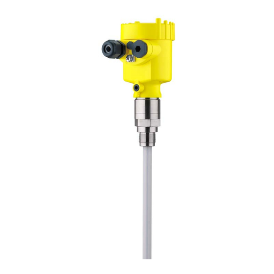
The VEGACAP 64 consists of the components: • Process fitting with probe • Housing with electronics • Housing lid Fig. 1: VEGACAP 64, rod version with plastic housing Housing lid Housing with electronics 3 Process fitting Type label The type label contains the most important data for identification and use of the instrument: VEGACAP 64 • Transistor (NPN/PNP) -
Page 8: Principle Of Operation
Principle of operation Application area VEGACAP 64 is a point level sensor for use in non-abrasive liquids and bulk solids. The rod probe is fully insulated and due to its construction is suitable for all viscous and adhesive products. -
Page 9: Adjustment
The capacitance change is converted by the electronics module into a switching command. Voltage supply VEGACAP 64 is a compact instrument, i.e. it can be operated without external evaluation system. The integrated electronics evaluates the level signal and outputs a switching signal. With this switching signal, a connected device can be operated directly (e.g. -
Page 10: Accessories And Replacement Parts
The protective cover protects the sensor housing against soiling and intense heat from solar radiation. You will find additional information in the supplementary instructions manual "Protective cover" (Document-ID 34296). Flanges Screwed flanges are available in different versions according to the following standards: DIN 2501, EN 1092-1, BS 10, ASME B 16.5, JIS B 2210-1984, GOST 12821-80. You can find additional information in the supplementary instructions manual "Flanges according to DIN-EN-ASME-JIS". VEGACAP 64 • Transistor (NPN/PNP) -
Page 11: Mounting
(e.g. through cleaning processes) or on cooled or heated vessels. To maintain the housing protection, make sure that the housing lid is closed during operation and locked, if necessary. Make sure that the degree of contamination specified in chapter "Technical data" meets the existing ambient conditions. VEGACAP 64 • Transistor (NPN/PNP) - Page 12 Prior to setup you have to replace these protective caps with ap- proved cable glands or close the openings with suitable blind plugs. VEGACAP 64 • Transistor (NPN/PNP)
-
Page 13: Mounting Instructions
Agitators and fluidization Due to the effects of agitators, equipment vibration or similar, the level switch can be subjected to strong lateral forces. For this reason, do not use an overly long electrode for VEGACAP 64, but check if you can mount a short level switch on the side of the vessel in horizontal position. Extreme vibration caused by the system, e.g. due to agitators or turbulence in the vessel from fluidisation, can cause the probe of VEGACAP 64 to vibrate in resonance. - Page 14 Torque with PTFE plated To compensate the material-specific preload loss due to sealing ma- flanges terials, you have to additionally use disc springs for fastening flange screws on PTFE coated flanges. Tighten the screws moderately with the torque stated in the technical data. Depending on the process and ambient conditions, this value can vary. In individual cases you should occasionally check the tightness on site. VEGACAP 64 • Transistor (NPN/PNP)
-
Page 15: Connecting To Power Supply
Voltage supply Take note of the general installation regulations. As a rule, connect VEGACAP 64 to vessel ground (PA), or in case of plastic vessels, to the next ground potential. On the side of the instrument housing there is a ground terminal between the cable entries. This connection serves to drain off electrostatic charges. -
Page 16: Wiring Plan, Single Chamber Housing
Wiring plan, single chamber housing Housing overview Fig. 8: Material versions, single chamber housing Plastic (not with dust-Ex) Aluminium Stainless steel Filter element for pressure compensation or blind plug with version IP 66/ IP 68, 1 bar VEGACAP 64 • Transistor (NPN/PNP) - Page 17 Connection terminals Control lamp Wiring plan We recommend connecting VEGACAP 64 in such a way that the switching circuit is open when there is a level signal, line break or failure (safe state). The instrument is used to control relays, contactors, magnet valves, warning lights, horns as well as PLC inputs.
- Page 18 5 Connecting to power supply Fig. 10: Wiring plan Voltage supply 1 2 3 4 Fig. 11: NPN action 1 2 3 4 Fig. 12: PNP action VEGACAP 64 • Transistor (NPN/PNP)
-
Page 19: Wiring Plan - Version Ip 66/Ip 68, 1 Bar
Wire assignment, con- nection cable Fig. 13: Wire assignment connection cable. The numbers of the wires corre- spond to the terminals of the instrument. brown (+) voltage supply White Yellow blue (-) voltage supply Shielding VEGACAP 64 • Transistor (NPN/PNP) -
Page 20: Setup
Note: As a rule, always set the mode with the mode switch (3) before start- ing setup VEGACAP 64. The switching output will change if you set the mode switch (3) afterwards. This could possibly trigger other con- nected instruments or devices. - Page 21 In some cases the lowest range (range 1 = highest sensitivity) is not sufficient to adjust the full switch point. This would make another filling procedure necessary. For this reason we recommend setting and noting the empty switching point in all three meas. ranges. Set the meas. range se- VEGACAP 64 • Transistor (NPN/PNP)
- Page 22 1. Set mode switch (3) to mode min. detection) 2. Set meas. range selection switch (2) to range 1. 3. Lower the level to the requested min. level. 4. Turn the potentiometer (1) to 0, the control lamp (6) lights green. VEGACAP 64 • Transistor (NPN/PNP)
-
Page 23: Function Table
Control lamp Mode max. closed Overflow protection Green Mode max. open Overflow protection Mode min. closed Dry run protection Green Mode min. open Dry run protection Failure of the supply volt- open (min./max. mode) Fault open flashes red VEGACAP 64 • Transistor (NPN/PNP) -
Page 24: Maintenance And Fault Rectification
24 hour service hotline Should these measures not be successful, please call in urgent cases the VEGA service hotline under the phone no. +49 1805 858550. The hotline is manned 7 days a week round-the-clock. Since we offer this service worldwide, the support is only available in the English language. The service is free, only standard call charges are incurred. -
Page 25: Exchange Of The Electronics Module
Downloads. Proceed as follows: 1. Switch off power supply 2. Unscrew the housing lid 3. Lift the opening levers of the terminals with a screwdriver 4. Pull the connection cables out of the terminals 5. Loosen the two screws with a screw driver (Torx size T10 or slot VEGACAP 64 • Transistor (NPN/PNP) - Page 26 13. Check the hold of the wires in the terminals by lightly pulling on them 14. Check cable gland on tightness. The seal ring must completely encircle the cable. 15. Mount the probe into the vessel. Make sure that the probe is uncovered. VEGACAP 64 • Transistor (NPN/PNP)
-
Page 27: How To Proceed If A Repair Is Necessary
Clean the instrument and pack it damage-proof • Attach the completed form and, if need be, also a safety data sheet outside on the packaging • Please contact the agency serving you to get the address for the return shipment. You can find the agency on our home page www.vega.com. VEGACAP 64 • Transistor (NPN/PNP) -
Page 28: Dismount
These may be used only for privately used products according to the WEEE directive. Correct disposal avoids negative effects on humans and the environ- ment and ensures recycling of useful raw materials. Materials: see chapter "Technical data" If you have no way to dispose of the old instrument properly, please contact us concerning return and disposal. VEGACAP 64 • Transistor (NPN/PNP) -
Page 29: Supplement
60 Nm (44.25 lbf ft) Max. torque (process fitting - thread) 100 Nm (74 lbf ft) Torque for NPT cable glands and Conduit tubes Ʋ Plastic housing max. 10 Nm (7.376 lbf ft) Ʋ Aluminium/Stainless steel housing max. 50 Nm (36.88 lbf ft) VEGACAP 64 • Transistor (NPN/PNP) - Page 30 -50 … +150 °C (-58 … +302 °F) 316L Process temperature (thread or flange -50 … +200 °C (-58 … +392 °F) temperature) with temperature adapter (option) Process temperature VEGACAP 64 of St -20 … +150 °C (-4 … +302 °F) C22.8 Distance from the process fittings to the set switching point. Distance from the process fittings to the set switching point. VEGACAP 64 • Transistor (NPN/PNP)
- Page 31 1000 m (3280 ft) Ʋ Min. bending radius 25 mm (0.984 in) with 25 °C (77 °F) Ʋ Diameter approx. 8 mm (0.315 in) Ʋ Colour - standard PE Black Ʋ Colour - standard PUR Blue Depending on the version M12 x 1, according to ISO 4400, Harting, 7/8" FF. VEGACAP 64 • Transistor (NPN/PNP)
- Page 32 Instruments with approvals can have different technical specifications depending on the version. For that reason the associated approval documents of these instruments have to be carefully noted. They are part of the delivery or can be downloaded under www.vega.com "Instrument search (serial number)" as well as in the general download area. A suitable cable is required for maintaining the protection rating.
-
Page 33: Dimensions
(5.91") (4.06") ø 77 mm ø 84 mm (3.03") (3.31") M20x1,5 M20x1,5 M20x1,5 Fig. 30: Housing versions with protection rating IP 66/IP 68 (1 bar) Stainless steel single chamber (precision casting) Aluminium - single chamber VEGACAP 64 • Transistor (NPN/PNP) - Page 34 9 Supplement A, G 1 A, G 1 ø16mm ( ") Fig. 31: VEGACAP 64, threaded version G1 (ISO 228 T1) Sensor length, see chapter "Technical data" L1 active length VEGACAP 64 • Transistor (NPN/PNP)
- Page 35 9 Supplement ø 40 mm (1.58") Fig. 32: Temperature adapter VEGACAP 64 • Transistor (NPN/PNP)
-
Page 36: Industrial Property Rights
Les lignes de produits VEGA sont globalement protégées par des droits de propriété intellec- tuelle. Pour plus d'informations, on pourra se référer au site www.vega.com. VEGA lineas de productos están protegidas por los derechos en el campo de la propiedad indus- trial. Para mayor información revise la pagina web www.vega.com. -
Page 37: Vegacap 64 • Transistor (Npn/Pnp)
Notes VEGACAP 64 • Transistor (NPN/PNP) - Page 38 Notes VEGACAP 64 • Transistor (NPN/PNP)
- Page 39 Notes VEGACAP 64 • Transistor (NPN/PNP)
- Page 40 Subject to change without prior notice © VEGA Grieshaber KG, Schiltach/Germany 2017 VEGA Grieshaber KG Phone +49 7836 50-0 Am Hohenstein 113...
Need help?
Do you have a question about the VEGACAP 64 and is the answer not in the manual?
Questions and answers