Table of Contents
Advertisement
Quick Links
Advertisement
Table of Contents

Subscribe to Our Youtube Channel
Related Manuals for Kendal Lighting AC-20452


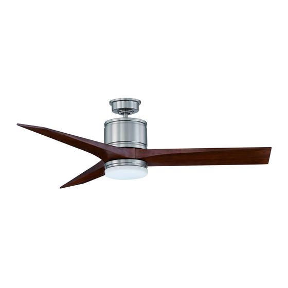
Summary of Contents for Kendal Lighting AC-20452
- Page 1 READ AND SAVE THESE INSTRUCTIONS INSTALLATION INSTRUCTIONS Model: AC-20452 KENDAL LIGHTING Kendal Lighting (BC) Inc. #110, 6780 Dennett Place Delta, BC V4G 1N4 Canada Tel: (604) 952-5510 Fax: (604) 952-5513 UL and cUL Listed Model: AC-387 Weight of Fan:...
-
Page 2: Tools And Materials Required
1. TOOLS AND MATERIALS REQUIRED Philips screw driver Flat screw driver 11 mm wrench Step ladder Wire cutters 2. PACKAGE CONTENTS Unpack your fan and check the contents. You should have the following items; Blade set (3) Hanger bracket assembly Downrod Coupling cover Fan motor assembly... -
Page 3: Safety Rules
3. SAFETY RULES 1. To reduce the risk of electric shock, insure 8. Avoid placing objects in the path of the electricity has been turned off at the circuit blades. breaker or fuse box before beginning. 9. To avoid personal injury or damage to the 2. -
Page 4: Mounting Options
4. MOUNTING OPTIONS If there isn't an existing CUL listed mounting box, then read the following instructions. Disconnect the power by removing fuses or turning off circuit breakers. Outlet box Secure the outlet box directly to the building structure. Use appropriate fasteners and building materials. -
Page 5: Hanging The Fan
5. HANGING THE FAN Ceiling hanger REMEMBER to turn off the power. Follow the bracket steps below to hang your fan properly: Ceiling canopy Step 1. Remove the decorative canopy bottom cover from the canopy by turning the cover counter clockwise. (Fig. 5) Canopy cover Figure 5 Step 2. -
Page 6: Make The Electric Connections
6. MAKE THE ELECTRIC CONNECTIONS Code switch WARNING: To avoid possible electrical shock, be sure electricity is turned off at the main fuse box before wiring. NOTE: This remote control unit is equipped with 16 code combinations to prevent possible Figure 9 interference from or to other remote units. -
Page 7: Installation Of Safety Support
Note: Fan must be installed at a maximum distance of 20 feet from the transmitting unit for proper signal transmission between the transmitting unit and the fan's receiving unit. 7. INSTALLATION OF SAFETY SUPPORT Attach the lag bolt and flat washer to ceiling joist. -
Page 8: Attaching The Fan Blades
9. ATTACHING THE FAN BLADES Fasten blade assembly to motor using the flat washers and screws supplied. (Fig. 14) CAUTION: Make sure screws tightened securely. Flat washers Blade Screws Figure 14 10. ATTACHING THE MOUNTING PLATE 1. Remove 1 of 3 screws from the mounting ring and loosen the other 2 screws. - Page 9 11. ATTACHING THE LIGHT PLATE NOTE: Before starting installation, disconnect the power by turning off the circuit breaker or removing the fuse at fuse box. Turning power off using the fan switch is not sufficient to prevent electric shock. Raise and hold the light plate close to the mounting plate and proceed to do the wire connections, Connect the white wire connectors from the light plate and fan, follow the same...
- Page 10 13. INSTALLING THE Outlet box TRANSMITTER Switch HOLDER Wall plate Select a location to install your remote control system transmitter. You can replace an existing wall switch or, install the transmitter on ANY flat surface. Option 1: Install the cremote ontrol system using an existing wall switch outlet box.
-
Page 11: Installing The Battery
14. INSTALLING THE BATTERY Remove the back cover on the transmitter and install both, 3 volt (#2032) batteries that were included with the remote control. Make sure the + sign is facing up. (Fig. 21) 15. OPERATING YOUR TRANSMITTER Figure 21 Restore power to ceiling fan and test for proper operation. -
Page 12: Care Of Your Fan
16. CARE OF YOUR FAN Here are some suggestions to help you maintain your fan. 1. Because of the fan's natural movement, some connections may become loose. Check the support connections, brackets, and blade attachments twice a year. Make sure they are secure. -
Page 13: Troubleshooting
17. TROUBLESHOOTING Problem Solution Fan will not start. 1. Check circuit fuses or breakers. 2. Check line wire connections to the fan and switch wire connections in the switch housing. CAUTION: Make sure main power is off. 3. Check to make sure the dip switches from the transmitter and receiver are set to the same frequency.
Need help?
Do you have a question about the AC-20452 and is the answer not in the manual?
Questions and answers