
Related Manuals for Kramer VP-733


Summary of Contents for Kramer VP-733
- Page 1 USER MANUAL MODEL: VP-733 Presentation Switcher/Dual Scaler P/N: 2900-300547 Rev 1 www.kramerAV.com...
-
Page 6: Table Of Contents
Switching the Inputs Preview/Program Operation Mode The PIP Operation Mode Locking and Unlocking the Front Panel The Infrared Remote Control Transmitter Configuring the VP-733 via the OSD MENU Screens The Input Screen The Picture Screen The Output Screen The PIP Screen... - Page 7 Kramer Protocol 3000 Syntax 12.3 Protocol 3000 Commands Figures Figure 1: VP-733 Presentation Switcher/Dual Scaler Front Panel Figure 2: VP-733 Presentation Switcher/Dual Scaler Rear Panel Figure 3: Connecting to the VP-733 Rear Panel Figure 4: UNIV 15-pin HD Connector Pinout...
- Page 8 Figure 46: The EDID Page – Selecting a Resolution to copy to an Input Figure 47: The Advanced Settings Page Figure 48: The Custom Resolutions Page Figure 49: The Custom Resolutions Page – Current Parameters Figure 50: The Security Page Figure 51: The About Page VP-733 – Contents...
-
Page 9: Introduction
Introduction Welcome to Kramer Electronics! Since 1981, Kramer Electronics has been providing a world of unique, creative, and affordable solutions to the vast range of problems that confront the video, audio, presentation, and broadcasting professional on a daily basis. In recent years, we have redesigned and upgraded... -
Page 10: Getting Started
Avoid interference from neighbouring electrical appliances that may adversely influence signal quality • Position your Kramer VP-733 away from moisture, excessive sunlight and dust This equipment is to be used only inside a building. It may only be connected to other equipment that is installed inside a building. -
Page 11: Recycling Kramer Products
Kramer Electronics has made arrangements with the European Advanced Recycling Network (EARN) and will cover any costs of treatment, recycling and recovery of waste Kramer Electronics branded equipment on arrival at the EARN facility. For details of Kramer’s recycling arrangements in your particular country go to our recycling pages at www.kramerav.com/support/recycling. -
Page 12: Overview
Overview The Kramer VP-733 is a 12-input Presentation Switcher/Dual Scaler for a wide variety of presentation and multimedia applications. The VP-733 has four HDMI, two DisplayPort, two HDBT and four user-definable (universal) analog video inputs (each can be set as computer graphics, composite video, s-Video (Y/C) or component video). - Page 13 BLANK and FREEZE buttons for the preview and program modes, a RESET TO XGA/720P button (to hardware-reset the output resolution); and a PANEL LOCK button • User-friendly AP for Text Overlay support • Firmware Upgrade – Ethernet-based, via a user-friendly software upgrade tool VP-733 – Overview...
-
Page 14: Defining The Vp-733 Presentation Switcher/Dual Scaler
• Via the Ethernet using built-in user-friendly Web pages The VP-733 is housed in a 19” 1U rack mountable enclosure, with rack “ears” included, and is fed from a 100-240 VAC universal switching power supply. Defining the VP-733 Presentation Switcher/Dual Scaler This section defines the VP-733. -
Page 15: Figure 1: Vp-733 Presentation Switcher/Dual Scaler Front Panel
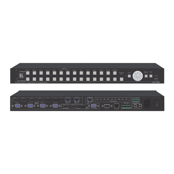
Figure 1: VP-733 Presentation Switcher/Dual Scaler Front Panel Feature Function IR Receiver Receives signals from the remote control transmitter Lights red when the unit accepts IR remote commands UNIV 1 Press to select the computer graphics/composite video / s-Video / component video source (configured via the OSD... - Page 16 Feature Function MENU Button Press to display the OSD menu screen. Press again to return to normal operation ENTER Button Press to move to the next level in the OSD screen or to accept a new parameter Decreases the range by one step in the OSD screen or moves to the previous level in the OSD screen Button Decreases the volume level, when not in the OSD menu Moves up one step (in the same level) in the OSD screen, or moves to the previous slide when running a slideshow...
-
Page 17: Figure 2: Vp-733 Presentation Switcher/Dual Scaler Rear Panel
Connect to the DP 1 source (from 1 to 2) HDBT IN 1 Connector Connect to an HDBT Transmitter (for example, the Kramer TP-580Txr) to pass audio and video signals as well as serial commands (from 1 to 2) PROG HDBT OUT... -
Page 18: Installing In A Rack
Installing in a Rack This section provides instructions for rack mounting the unit. VP-733 - Installing in a Rack... -
Page 19: Connecting The
Connecting the VP-733 Always switch off the power to each device before connecting it to your VP-733. After connecting your VP-733, connect its power and then switch on the power to each device. To connect the VP-733 as illustrated in the example in... - Page 20 “R+” and the “R-” terminal block connectors. Do not Ground the loudspeakers. Connect the power cord. We recommend that you use only the power cord that is supplied with this machine. VP-733 - Connecting the VP-733...
-
Page 21: Universal Connector Pinout
▪ The ETHERNET port, see Section 5.4 Figure 3: Connecting to the VP-733 Rear Panel Universal Connector Pinout This section describes the UNIV connectors from 1 to 4. Each connector can be set as computer graphics, composite video, s-Video (Y/C) or component video. -
Page 22: Connecting To The Vp-733 Via
Connecting to the VP-733 via RS-232 You can connect to the VP-733 via an RS-232 connection using, for example, a PC. Note that a null-modem adapter/connection is not required. To connect to the VP-733 via RS-232: • Connect the RS-232 9-pin D-sub rear panel port on the VP-733 unit via a... -
Page 23: Figure 7: Local Area Connection Properties Window
5.4.1 Connecting the Ethernet Port Directly to a PC You can connect the Ethernet port of the VP-733 directly to the Ethernet port on your PC using a crossover cable with RJ-45 connectors. This type of connection is recommended for identifying the VP-733 with the factory configured default IP address. -
Page 24: Figure 8: Internet Protocol Version 4 Properties Window
Protocol Version 4 (TCP/IPv4) depending on the requirements of your IT system. Click Properties. The Internet Protocol Properties window relevant to your IT system appears as shown in Figure 8 Figure Figure 8: Internet Protocol Version 4 Properties Window VP-733 - Connecting the VP-733... -
Page 25: Figure 9: Internet Protocol Version 6 Properties Window
Select Use the following IP Address for static IP addressing and fill in the details as shown in Figure For TCP/IPv4 you can use any IP address in the range 192.168.1.1 to 192.168.1.255 (excluding 192.168.1.39) that is provided by your IT department. VP-733 – Connecting the VP-733... -
Page 26: Figure 10: Internet Protocol Properties Window
Click Close. 5.4.2 Connecting the Ethernet Port via a Network Hub or Switch You can connect the Ethernet port of the VP-733 to the Ethernet port on a network hub or using a straight-through cable with RJ-45 connectors. 5.4.3 Control Configuration via the Ethernet Port To control several units via Ethernet, connect the Master unit (Device 1) via the Ethernet port to the Ethernet port of your PC. -
Page 27: Presentation Switcher / Scaler Buttons
Presentation Switcher / Scaler Buttons The VP-733 includes the following front panel buttons: • 12 PROGRAM INPUT selector buttons • 12 PIP/PREVIEW INPUT selector buttons • A PREVIEW MODE button to toggle between the PIP and PREVIEW modes • PROGRAM and PREVIEW separate BLANK and FREEZE buttons •... -
Page 28: Preview/Program Operation Mode
PIP input appears as an insert over the program display when the PIP is ON (see Section 6.3). The VP-733 has several outputs: two PROGRAM outputs (HDMI 2 and DP) one PREVIEW output (PC) and HDMI 1 which can be assigned to be either PROGRAM or PREVIEW (see Section 7.3). - Page 29 PIP icon (see Figure 17). Select On/Off and set the PIP to ON. Select Source and press ENTER. Use the buttons to select the PIP Source from the drop-down list box, and press ENTER. VP-733 – Presentation Switcher / Scaler Buttons...
-
Page 30: Locking And Unlocking The Front Panel
Locking and Unlocking the Front Panel To prevent changing the settings accidentally or tampering with the unit via the front panel buttons or the remote control transmitter, lock your VP-733. Unlocking releases the protection mechanism. When the front panel is locked, control is still available via RS-232 and/or the Ethernet. -
Page 31: The Infrared Remote Control Transmitter
The Infrared Remote Control Transmitter You can control the VP-733 remotely from the infrared remote control transmitter which is powered by two AAA size 1.5V DC batteries. The IR remote control transmitter has a range of up to 15 meters and delivers instantaneous results. -
Page 32: Configuring The Vp-733 Via The Osd Menu Screens
Screens The VP-733 uses an on-screen display (OSD) menu for system configuration. The menu appears as an overlay over any images that are output from the VP-733. There are seven sub-menus that are used to configure the VP-733. You can activate and navigate these menus from the front panel buttons, or from the IR remote control. -
Page 33: The Input Screen
We recommend that you update the Hpos, Vpos, Frequency and Phase values (in the Fine-tune OSD menu) only after Auto Image is complete (if necessary). Enabled for VGA VP-733 – Configuring the VP-733 via the OSD MENU Screens... -
Page 34: The Picture Screen
Mosquito NR – Set the Mosquito noise reduction level: Off, Low, Medium, High Enabled for analog inputs only Set the block noise reduction level: Off, On Enabled for analog inputs only VP-733 - Configuring the VP-733 via the OSD MENU Screens... -
Page 35: The Output Screen
Set zoom to 100% 150%, 200%, 225%, 250%, 275%, 100% 300%, 325%, 350%, 375%, 400% or click custom to set the custom zoom and enable Zoom H-Pan and Zoom V- VP-733 – Configuring the VP-733 via the OSD MENU Screens... - Page 36 Set the HDMI 2 output type to Auto, HDMI or DVI Type Test Set the test pattern to Colorbar, SMPTE, Greyscale, Picture Border, Pattern Multiburst, Ramps, H-pattern, Setup, or set to Off VP-733 - Configuring the VP-733 via the OSD MENU Screens...
- Page 37 You can configure the aspect ratio of any output image to fit your application. The VP-733 offers six different aspect ratio settings: Best Fit, Letterbox, Follow Output, Virtual Wide, Follow Input, and Custom. Here is how each of these settings works.
-
Page 38: The Pip Screen
Set the vertical position of the PIP on the display: 0 – 128 V-Position H-Size – Set custom size: 1 – 255 (up to 960 pixels) Custom V-Size – Set custom size: 1 – 255 (up to 540 pixels) VP-733 - Configuring the VP-733 via the OSD MENU Screens... -
Page 39: The Audio Screen
Input Source menu. When Off selecting a different video signal will not change the audio setting and it can be selected via the Input Source menu separately VP-733 – Configuring the VP-733 via the OSD MENU Screens... -
Page 40: The Setup Screen
Frame Lock mode unless all sources are frame synchronized • If VP-733 can lock the input then the output will follow • If VP-733 cannot lock the input, then the output will not change. The info menu will display one of the... - Page 41 Set the following Ethernet settings: DHCP (DHCP will automatically Setting assign an IP address) On or Off, IP Address, Subnet Mask and Gateway Factory Select Yes to reset your VP-733 to its preset default settings Reset Advanced Opens the advanced setup menu screen, which includes the: Mode Setup (Section 7.6.1), OSD...
- Page 42 3. Click Logo Download item. The BMP image appears 4. Select the BMP file and press the Enter button When Custom is selected in the Logo item menu this logo will appear after powering up the device VP-733 - Configuring the VP-733 via the OSD MENU Screens...
- Page 43 Set the port for data tunneling: HDBT IN1, HDBT IN2 or HDBT OUT Tunneling HDBT Select the port tunneling port number (00000 to 65535) 05050 Tunneling Port Firmware For factory use Default Download Path VP-733 – Configuring the VP-733 via the OSD MENU Screens...
-
Page 44: Figure 20: Text Overlay Application Screen
Using Text Overlay The text overlay feature is accessed via the Application Program (AP). Running this AP with the PC connected to the VP-733 lets you display text over the screen, with features including text color and speed, transparency, text position and repetition. - Page 45 When selected, set the COM port and Baud Rate (9600) to connect via the RS-232 connector Current Status Indicates whether there is a valid connection to the VP-733 Scrolling Mode Area Speed Dropdown Box Set the speed at which the text moves on the display...
- Page 46 Read VGA EDID connected to the VGA output. The EDID is stored as a custom output resolution. This allows, for example, automatic handling of LED screens that support very low non-standard resolutions VP-733 - Configuring the VP-733 via the OSD MENU Screens...
-
Page 47: Figure 21: Active Video Functions
Otherwise it is disabled. Select the native resolution: Default 1024x768@60, 1280x800@60, 1280x1024@60, Default 1366x768@60, 1440x900@60, 1400x1050@60, 1600x900@60 (R), 1600x1200@60, 1680x1050@60, 1920x1080@60, 1920x1200@60Hz (R), 720p50, 720p60, 1080p50, 1080p60, 2048x1080@50Hz, 2048x1080@60Hz, 3840x2160x30Hz VP-733 – Configuring the VP-733 via the OSD MENU Screens... -
Page 48: The Info Screen
Preview Source, PIP Source, Program Output, Preview Output, HDMI Output, Sync Mode, MCU Version, OSD Version, FPGA Version, Slave Version CPLD IO Version, CPLD KPD Version, Dynamic IP/Static IP. Figure 22: Information Screen VP-733 - Configuring the VP-733 via the OSD MENU Screens... -
Page 49: Firmware Upgrade
Kramer Web site at kramerav.com/support/downloads.asp You can upgrade the VP-733 via the VP Download tool, which can be downloaded from our Web site. After downloading this upgrade tool: Connect the VP-733 to your PC via the Ethernet. -
Page 50: Using The Embedded Web Pages
Using the Embedded Web Pages The Web pages let you control the VP-733 via the Ethernet. The Web pages include all the OSD items and more, and are accessed using a Web browser and an Ethernet connection. Note that the Web page features are described in more detail in the OSD... -
Page 51: The Routing & Scaling Page
The Program Routing and Scaling Page Figure 24 shows the Program Routing & Scaling page that is also the first page that appears following the loading page. The column on the left shows the Program VP-733 – Using the Embedded Web Pages... -
Page 52: Figure 24: The Routing & Scaling Page With Web Page List On The Left
When in the PIP mode, the Program tab shows the various PIP options (see Figure 26) or a single page with no PIP displaying (see Figure 25). In the PIP mode the preview output resolution will always be Single Picture. VP-733 - Using the Embedded Web Pages... -
Page 53: Figure 26: The Routing & Scaling Page - Main And Pip Windows
9.2.2 The Preview Routing and Scaling Page The Preview Router & Scaling page is enabled when resolution is other than Single Picture, meaning that the program and preview outputs can show different outputs. VP-733 – Using the Embedded Web Pages... -
Page 54: Figure 27: The Preview Routing & Scaling Page - Disabled In Pip Mode
You can also move the image by pressing the mouse button and moving the image about. The image size and position are indicated at the image top right and for each window, the top VP-733 - Using the Embedded Web Pages... -
Page 55: Figure 29: The Routing & Scaling Page - Single Program/Preview Window
Figure 30: The Routing & Scaling Page – Moving the PIP Window 9.2.5 Setting the Output Resolution The output resolution can be selected from the Resolution drop-down box: VP-733 – Using the Embedded Web Pages... -
Page 56: Figure 31: The Routing & Scaling Page - Selecting The Output Resolution
Figure 32: The Routing & Scaling Page – The Swap Inputs 9.2.7 The Lower Buttons Bar The lower buttons bar lets you perform quick and easy setups: Figure 33: The Routing & Scaling Page – Program Lower Buttons Bar VP-733 - Using the Embedded Web Pages... -
Page 57: Figure 34: The Routing & Scaling Page - Preview Lower Buttons Bar
Select freeze and/or blank effects Select a test pattern 9.2.8 Store and Recall a Setup You can store or recall a setup via the store and recall buttons: Store button Recall button To save a preset:. VP-733 – Using the Embedded Web Pages... -
Page 58: Figure 35: The Routing & Scaling Page - Storing And Recalling A Preset
Click the pen icon on the input label to edit the input. The Web page moves to the Input Settings page (see Section 9.4). Figure 37: The Routing & Scaling Page – Editing an Input VP-733 - Using the Embedded Web Pages... -
Page 59: The Device Settings Page
You can change the Ethernet parameters (DHCP box needs to be checked) by typing the change and clicking the Apply button. Note that: • After changing the IP number, you need to reload the Web page with the new IP number VP-733 – Using the Embedded Web Pages... -
Page 60: Figure 39: The Device Settings Page - The Information Window
Figure 39: The Device Settings Page – the Information Window 9.3.3 Factory Reset Click the Factory reset button to reset the device. The following window appears: Figure 40: The Device Settings Page – Factory Reset Click OK to start factory reset. VP-733 - Using the Embedded Web Pages... -
Page 61: The Input Settings Page
UNIV, see Section 7.1 HDCP (HDMI & Set to ON or OFF DisplayPort) Adjust the image parameters Horizontal and Vertical Position, Fine-Tune Frequency and Phase, for VGA images, see Section 7.2 VP-733 – Using the Embedded Web Pages... - Page 62 Section 7.1 Auto Image Section 7.6 Program Volume Set the input program volume Preview Volume Set the input preview volume You can set the source label by typing the label name and saving it: VP-733 - Using the Embedded Web Pages...
-
Page 63: The Output Settings Page
HDMI 2 Type Test Patterns Set the test pattern to Colorbar, SMPTE, Greyscale, Picture Border, Multiburst, Ramps, H-pattern, Setup, or set to Off Program audio slider Use to set the Program output volume VP-733 – Using the Embedded Web Pages... -
Page 64: The Audio Settings Page
Set the delay time (in ms) Audio Follow Video Set to Off or On Program input Set the program input volume (analog, S/PDIF or embedded) Volume Program Output Set the program output volume Volume VP-733 - Using the Embedded Web Pages... -
Page 65: The Miscellaneous Video Settings Page
Section 7.6 Frame Latency Set to Best Quality or Fast, see Section 7.6 Hot Plugs Set Hot Plug On or Off for HDMI1 to HDMI 4, DisplayPort 1 and DisplayPort 2, see Section 7.6 VP-733 – Using the Embedded Web Pages... -
Page 66: The Edid Management Page
The EDID page lets you read the EDID from any of the outputs (HDMI 1, HDMI 2, DP and VGA), from a list of default resolutions or from a file in your PC (Browse). The selected EDID can be copied to a selected input. Figure 45: The EDID Page VP-733 - Using the Embedded Web Pages... - Page 67 Figure 46: The EDID Page – Selecting a Resolution to copy to an Input To copy, click the Copy button. Figure 46 shows how to select one of the outputs from the list and select an input. To copy, click the Copy button: VP-733 – Using the Embedded Web Pages...
-
Page 68: The Advanced Settings Page
Select On, Off or Custom, see Section 7.6.3 Overlay Select to Off, Text or Logo, see Section 7.6.3 Blank mode Select Blank & Mute, Blank or Mute to determine the behavior of the BLANK front panel button VP-733 - Using the Embedded Web Pages... -
Page 69: The Custom Resolutions Page
49) or type it in manually. You can save up to four custom settings each for the input and the output (see Sections 7.6.4 and 7.6.5). Figure 48: The Custom Resolutions Page Figure 49: The Custom Resolutions Page – Current Parameters VP-733 – Using the Embedded Web Pages... -
Page 70: The Security Page
Figure 50: The Security Page 9.12 The About Page The VP-733 About page lets you view the Web page version and Kramer Electronics Ltd details. Figure 51: The About Page VP-733 - Using the Embedded Web Pages... -
Page 71: Technical Specifications
3.56 kg (7.85lbs) approx. weight: Included rack ears, IR remote control, 2 sets of C-GM/3RVF-1 cables, power cord Accessories: Specifications are subject to change without notice For the most updated resolution list, go to our Web site at www.kramerav.com VP-733 – Technical Specifications... -
Page 72: Default Communication Parameters
VESA 1440x900 VESA 1024x768 VESA 1440x900 VESA 1024x768 VESA 1400x1050 VESA 1024x768 Mac19 1400x1050 VESA 1024x768 VESA 1600x900 VESA 1024x800 1600x1200 VESA 1152x864 VESA 1680x1050 VESA 1152x870 Mac21 1680x1050 VESA 1152x900 1920x1080 VESA 1152x900 1920x1200 VESA VP-733 - Technical Specifications... - Page 73 576i YPbPr 576p YPbPr Technical Specifications of the Component Input Signal Resolution Vertical Frequency (Hz) Remark 1080i YPbPr 1080i YPbPr 1080p YPbPr 1080p YPbPr 720p YPbPr 720p YPbPr 480i YPbPr 480p YPbPr 576i YPbPr 576p YPbPr VP-733 – Technical Specifications...
- Page 74 VESA 1024x768 VESA 1400x1050 VESA 1024x768 VESA 1400x1050 VESA 1024x768 Mac19 1600x900 VESA 1024x768 VESA 1600x1200 VESA 1024x800 1680x1050 VESA 1152x864 VESA 1680x1050 VESA 1152x870 Mac21 1920x1080 VESA 1152x900 1920x1200 VESA 1152x900 2048x1080 1280x720 VESA 2048x1080 VP-733 - Technical Specifications...
-
Page 75: Tables Of Supported Output Resolutions
1280x768 480p 1280x768 VESA 576p 1280x800 VESA 1080p 1280x1024 1080p Comp/YPbPr 1280x1024 VESA 480p 59.94 1280x1024 VESA 720p 59.94 1366x768 1080i 59.94 1366x768 VESA 1080p 23.98 1400x1050 1080p 1400x1050 VESA 1080p 29.97 1600x900 VESA 1080p 59.94 VP-733 – Technical Specifications... - Page 76 1280x1024 VESA 576p 1280x1024 VESA 1080p 1366x768 1080p 1366x768 VESA 480p 59.94 HDMI 1400x1050 720p 59.94 1400x1050 VESA 1080i 59.94 1600x900 VESA 1080p 23.98 1600x1200 1080p 1600x1200 VESA 1080p 29.97 1920x1080 VESA 1080p 59.94 1920x1200 VESA VP-733 - Technical Specifications...
-
Page 77: Communication Protocol
Example: get current Input 1 Source Type Send: Y113CR Reply: Z1103CRLF > Definition: : ASCII Code 0x20 CR: Ascii Code 0x0D CRLF : Ascii Code 0x0D+0x0A Go to www.kramerav.com/downloads/VP-733 to check for the latest VP-733 communication protocol. VP-733 – VP-733 Communication Protocol... -
Page 78: Command List
1. PIP mode: only freeze the PIP source 2. Dual resolution mode: freeze the Preview source Preview Mute key function Preview key function 0: Off 1: On If PIP is On, Preview will turn off PIP 0: Off Power 1: On VP-733 - VP-733 Communication Protocol... - Page 79 Input Auto Image (Enabled for VGA Input) 0~100 Picture Brightness 0~100 Picture Contrast 0~100 Picture Color 0~360 CVBS/YC Picture Hue 0~240 HDMI/VGA/Component 0~100 Picture Sharpness 0: Off Picture Temporal NR 1: Low HDMI input is disabled. VP-733 – VP-733 Communication Protocol...
- Page 80 28: 1920x1200@60Hz(R) 29: 2048x1080@50Hz 30: 2048x1080@60Hz 31: 3840x2160@24Hz 32: 3840x2160@25Hz 33: 3840x2160@29_97Hz 34: 3840x2160@30Hz 35: 4096x2160@24Hz 36: 480p@60Hz 37: 576p@50Hz 38: 720p@50Hz 39: 720p@60Hz 40: 1080i@50Hz 41: 1080i@60Hz 42: 1080p@50Hz 43: 1080p@60Hz 44: 1080p@24Hz 45: 480P@59.94Hz VP-733 - VP-733 Communication Protocol...
- Page 81 Aspect Ratio Custom H-Pan Zoom ! = 100% is disabled -16 ~ 16 Aspect Ratio should be Custom Aspect Ratio Custom H-Zoom can’t be 0 Aspect Ratio Custom V-Pan -16 ~ 16 Zoom ! = 100% is disabled VP-733 – VP-733 Communication Protocol...
- Page 82 0: PIP 1: P+P PIP Type (Enabled as PIP On) 2: Split 0: UNIV 1 1: UNIV 2 2: UNIV 3 PIP Source (Enabled as PIP On) 3: UNIV 4 4: HDMI 1 5: HDMI 2 VP-733 - VP-733 Communication Protocol...
- Page 83 -22~0~+22 Picture. HDMI1 output is set to Follow Preview Audio Preview Input Volume is available when the: Preview (VGA) output resolution is NOT set to Single -100~24 Picture. HDMI1 output is set to Follow Preview VP-733 – VP-733 Communication Protocol...
- Page 84 Setup - Save Setting 5: Profile 6 6: Profile 7 7: Profile 8 8: USB 0: Profile 1 1: Profile 2 2: Profile 3 Setup - Recall Setting 3: Profile 4 4: Profile 5 5: Profile 6 VP-733 - VP-733 Communication Protocol...
- Page 85 Setup - HDMI4 Input HDCP 1: On 0: Off Setup - DP1 Input HDCP 1: On 0: Off Setup - DP2 Input HDCP 1: On 0: Profile 1 1: Profile 2 Setup - Erase 2: Profile 3 VP-733 – VP-733 Communication Protocol...
- Page 86 Advanced: OSD – Menu Position 2: Top Right 3: Bottom Left 4: Bottom Right 0: 5 sec 1: 10 sec 2: 20 sec Advanced: OSD – Time Out(sec.) 3: 30 sec 4: 60 sec 5: 90 sec 6: Off VP-733 - VP-733 Communication Protocol...
- Page 87 640~1920 Advanced: Input Mode: HA (temp value, unless to run the Input mode save) <= (HT-92) 0: Negative polarity Advanced: Input Mode: HP (temp value, unless to run the Input mode save) 1: Positive polarity VP-733 – VP-733 Communication Protocol...
- Page 88 Advanced: Output Mode: Set Current (temp value, unless to run the Output mode save) Advanced: Output Mode: Read HDMI1 EDID Advanced: Output Mode: Read HDMI2 EDID Advanced: Output Mode: Read DP EDID Advanced: Output Mode: Read VGA EDID VP-733 - VP-733 Communication Protocol...
- Page 89 6: 1400x1050 60 7: 1600x900 60 8: 1600x1200 60 Advanced: Input EDID: HDMI2 Select Modeline 9: 1680x1050 60 10: 1920x1080 60 11: 1920x1200 60(RB) 12: 720P 50 13:720P 60 14:1080P 50 15:1080p 60 16:2K 50 17:2K 60 VP-733 – VP-733 Communication Protocol...
- Page 90 Advanced: Input EDID: HDMI4 Select Modeline 9: 1680x1050 60 10: 1920x1080 60 11: 1920x1200 60(RB) 12: 720P 50 13:720P 60 14:1080P 50 15:1080p 60 16:2K 50 17:2K 60 0: Advanced: Input EDID: Advanced: Input EDID: DP1 DP1 Default VP-733 - VP-733 Communication Protocol...
- Page 91 10: 1920x1080 60 11: 1920x1200 60(RB) 12: 720P 50 13:720P 60 14:1080P 50 15:1080p 60 16:2K 50 17:2K 60 0: Advanced: Input EDID: UNIV1 Default Advanced: Input EDID: UNIV1 1: Advanced: Input EDID: UNIV1 Copy PC output VP-733 – VP-733 Communication Protocol...
- Page 92 UNIV4 Copy PC output 0: Default 1: 1024x768 60 2: 1280x800 60 3: 1280x1024 60 4: 1366x4768 60 Advanced: Input EDID: UNIV4 Select Modeline 5: 1440x900 60 6: 1400x1050 60 7: 1600x900 60 8: 1600x1200 60 VP-733 - VP-733 Communication Protocol...
- Page 93 40: 1600x900 60 R 41: 1600x1200 60 42: 1680x1050 60 R 43: 1680x1050 60 44: 1920x1080 60 45: 1920x1200 60 R 46: 2048x1080 50 47: 2048x1080 60 48: 3840x2160@24Hz 49: 3840x2160@25Hz 50: 3840x2160@29_97Hz 51: 3840x2160@30Hz VP-733 – VP-733 Communication Protocol...
- Page 94 19: 1152x864 75 20: 1152x870 75 Mac21 21: 1152x900 66 Sun 22: 1152x900 76 Sun 23: 1280x720 60 24: 1280x800 60 R 25: 1280x800 60 26: 1280x960 60 27: 1280x960 85 28: 1280x768 60 R VP-733 - VP-733 Communication Protocol...
- Page 95 0: 640x480 60 1: 640x480 67(Mac13) 2: 640x480 72 3: 640x480 75 4: 640x480 85 5: 720x400 70 PIP Input status 6: 720x400 85 7: 800x600 56 8: 800x600 60 9: 800x600 72 10: 800x600 75 VP-733 – VP-733 Communication Protocol...
- Page 96 151: 480p 60 152: 576i 50 153: 576p 50 154: 720p 50 155: 720p 60 156: 1080i 50 157: 1080i 60 158: 1080p 24 159: 1080p 50 160: 1080p 60 200: NTSC 201: PAL 202: PAL-M VP-733 - VP-733 Communication Protocol...
- Page 97 102: 720P 50 103: 720P 60 104: 1080i 50 105: 1080i 60 106: 1080P 50 107: 1080P 60 108: 1080P 24 109: 480P 59.94 110: 720P 59.94 111: 1080i 59.94 112: 1080P 23.98 113: 1080P 29.97 VP-733 – VP-733 Communication Protocol...
- Page 98 6: Program Blank & Freeze & Mute 7: Program Blank & Freeze Preview blank / freeze/ blank status 0: Preview off 1: Preview Blank & Mute 2: Preview Blank 3: Preview Mute 4: Preview Freeze & Mute VP-733 - VP-733 Communication Protocol...
- Page 99 4: 1366x768 60 5: 1440x900 60 6: 1400x1050 60 7: 1600x900 60(RB) Advanced: Input EDID: HDBT1 Select Modeline 8: 1600x1200 60 9: 1680x1050 60 10: 1920x1080 60 11: 1920x1200 60(RB) 12: 720P 50 13:720P 60 14:1080P 50 VP-733 – VP-733 Communication Protocol...
- Page 100 8: 1600x1200 60 Advanced: Input EDID: HDBT2 Select Modeline 9: 1680x1050 60 10: 1920x1080 60 11: 1920x1200 60(RB) 12: 720P 50 13: 720P 60 14: 1080P 50 15: 1080p 60 16: 2K 50 17: 2K 60 VP-733 - VP-733 Communication Protocol...
-
Page 101: Protocol 3000
VP-733 Presentation Switcher/Dual Scaler can be operated using the Kramer Protocol 3000 serial commands. The command framing varies according to how you interface with the VP-733. Generally, a basic video input switching command that routes a layer 1 video signal to HDMI out 1 from HDMI input 2 (ROUTE 1,1,2), is entered as follows: •... -
Page 102: Understanding Protocol 3000
Hercules) by connecting a PC to the serial or Ethernet port on your device. To enter CR press the Enter key (LF is also sent but is ignored by the command parser). Commands sent from various non-Kramer controllers (e.g., Crestron) may require special coding for some characters (such as, /X##). For more information, refer to your controller’s documentation. -
Page 103: Kramer Protocol 3000 Syntax
Commands in the string do not execute until the closing character is entered. A separate response is sent for every command in the chain. 12.2 Kramer Protocol 3000 Syntax The Kramer Protocol 3000 syntax uses the following delimiters: • CR = Carriage return (ASCII 13 = 0x0D) •... -
Page 104: Protocol 3000 Commands
This section includes the following commands: • Common Commands, Section 12.3.1. • Communication Commands, Section 12.3.2. • Routing Commands, Section 12.3.3. • System Commands, Section 12.3.1. • Video Commands, Section 12.3.2. • Audio Commands, Section 12.3.3. VP-733 - Protocol 3000... - Page 105 ~nn@FACTORYSPOKCR LF Notes This command deletes all user data from the device. The deletion can take some time. Your device may require powering off and powering on for the changes to take effect. K-Config Example “#FACTORY”,0x0D VP-733 – Protocol 3000...
- Page 106 – String of up to 19 printable ASCII chars Notes This command identifies equipment connected to Step-in master products and notifies of identity changes to the connected equipment. The Matrix saves this data in memory to answer REMOTE-INFO requests. K-Config Example “#MODEL?”,0x0D VP-733 - Protocol 3000...
- Page 107 Set: #SN?CR Get: Get device serial number Response ~nn@SNSPserial_numberCR LF Parameters serial_number – 11 decimal digits, factory assigned Notes This device has a 14-digit serial number, only the last 11 digits are displayed. K-Config Example “#SN?”,0x0D VP-733 – Protocol 3000...
- Page 108 If the port number you enter is already in use, an error is returned. The port number must be within the following range: 2000-(2^16-1). K-Config Example Set the Ethernet port protocol for TCP to port 12457: “#ETH-PORT 0,12457”,0x0D VP-733 - Protocol 3000...
- Page 109 A network gateway connects the device via another network, possibly over the Internet. Be careful of security problems. Consult your network administrator for correct settings. K-Config Example Set the gateway IP address to 192.168.0.1: “#NET-GATE 192.168.000.001”,0x0D VP-733 – Protocol 3000...
- Page 110 Functions Permission Transparency Set: NET-MAC? Get: End User Public Description Syntax Set: #NET-MAC?CR Get: Get MAC address Response ~nn@NET-MACSPmac_addressCR LF Parameters mac_address – unique MAC address. Format: XX-XX-XX-XX-XX-XX where X is hex digit K-Config Example “#NET-MAC?”,0x0D VP-733 - Protocol 3000...
- Page 111 Analog Preview: 0 (Analog1), 1 (Analog2), 2 (Analog3), 3 (Analog4), 4 (Analog5), 5 (Analog6), 6 (Analog7), 7 (Analog8), 8 (Analog9), 9 (Analog10), 10 (S/PDIF), 11 (Embedded) Notes This command replaces all other routing commands. K-Config Example Route Program HDBT1 input to the outputs: “#ROUTE 1,0,10”,0x0D VP-733 – Protocol 3000...
- Page 112 After execution, response is sent to the com port from which the Set/Get was received. After execution, response is sent to all com ports if VFRZ was set by any other external control device (button press, device menu and similar). K-Config Example Freeze Program outputs: “#ROUTE 1,0”,0x0D VP-733 - Protocol 3000...
- Page 113 Set view mode Get: #VIEW-MOD?Spout_idCR Get view mode Response ~nn@VIEW-MODSPout_id,modeCR LF Parameters out_id – 1 mode – 0 (PIP mode) main mode, 1 (PIP on), 2 (Preview) K-Config Example Set view mode to PIP on: “#VIEW-MOD 1,1”,0x0D VP-733 – Protocol 3000...
- Page 114 Mute the selected output #MUTE?SPchannelCR Get: Mute the selected output Response Set / Get: ~ nn@MUTESPchannel,mute_modeCR LF Parameters channel – 1 (Program), 2 (Preview) mute_mode –0 (Off, unmute), 1 (On, mute) K-Config Example Mute the preview outputs: “#MUTE 2,1”,0x0D VP-733 - Protocol 3000...
- Page 116 SAFETY WARNING Disconnect the unit from the power supply before opening and servicing For the latest information on our products and a list of Kramer distributors, visit our Web site where updates to this user manual may be found. We welcome your questions, comments, and feedback.
Need help?
Do you have a question about the VP-733 and is the answer not in the manual?
Questions and answers