Table of Contents
Advertisement
Quick Links
Advertisement
Table of Contents

Related Manuals for Ross OpenGear DEA-8805


Summary of Contents for Ross OpenGear DEA-8805
- Page 1 DEA-8805 Dual 3G/HD/SD SDI Equalizing Distribution Amplifier User Manual...
- Page 2 Ross has become well known for the Ross Video Code of Ethics. It guides our interactions and empowers our employees. I hope you enjoy reading it below. If anything at all with your Ross experience does not live up to your expectations be sure to reach out to us at solutions@rossvideo.com.
- Page 3 Ross Video. While every precaution has been taken in the preparation of this document, Ross Video assumes no responsibility for errors or omissions. Neither is any liability assumed for damages resulting from the use of the information contained herein.
- Page 4 Operation of this equipment in a residential area is likely to cause harmful interference in which case the user will be required to correct the interference at his own expense. Notice — Changes or modifications to this equipment not expressly approved by Ross Video Ltd. could void the user’s authority to operate this equipment. Canada This Class “A”...
- Page 5 To avoid the potential release of those substances into the environment and to diminish the need for the extraction of natural resources, Ross Video encourages you to use the appropriate take-back systems. These systems will reuse or recycle most of the materials from your end-of-life equipment in an environmentally friendly and health conscious manner.
-
Page 7: Table Of Contents
Contents Introduction Overview..........................1-2 Features........................1-2 Functional Block Diagrams ....................1-3 Dual 1x8 Configuration..................1-3 Dual 1x4 Configuration..................1-3 User Interfaces ........................1-4 DashBoard Control System ................... 1-4 Card-edge Monitoring ................... 1-4 SNMP Monitoring and Control ................1-4 Documentation Terms and Conventions................1-5 Installation Before You Begin ........................ - Page 8 Service Information Troubleshooting Checklist ....................6-2 Bootload Button..................... 6-2 Warranty and Repair Policy ....................6-3 ii • Contents DEA-8805 User Manual (Iss. 04)
-
Page 9: Introduction
A Word of Thanks Congratulations on choosing an openGear DEA-8805 Dual 3G/HD/SD Equalizing Amplifier. Thank you for joining the group of worldwide satisfied Ross Video customers! Should you have a question pertaining to the installation or operation of your DEA-8805, please contact us at the numbers listed on the back cover of this manual. -
Page 10: Overview
Overview Your DEA-8805 is a 3G/HD/SD Multi-Definition SDI distribution amplifier, capable of equalizing all common serial digital signals. An LED indicator at the front of the card identifies the presence of incoming video, simplifying system troubleshooting. Features The DEA-8805 includes the following features: •... -
Page 11: Functional Block Diagrams
Functional Block Diagrams The DEA-8805 can operate as an equalizing dual 1x8 or as a dual 1x4. The configuration depends on the rear module you are using. This section provides the block diagrams for all configurations. Dual 1x8 Configuration Figure 1.1 describes the workflow of the DEA-8805 with the 8320AR-302 Full Rear module. This configuration has the DEA-8805 operating as a dual equalizing 1x8 with HD-BNC connections. -
Page 12: User Interfaces
User Interfaces The following interfaces are available for control and monitoring of your DEA-8805. DashBoard Control System DashBoard enables you to monitor and control openGear frames and cards from a computer. DashBoard communicates with other cards in the openGear frame through the Network Controller Card. -
Page 13: Documentation Terms And Conventions
Documentation Terms and Conventions The following terms and conventions are used throughout this manual. Terms The following terms are used: • “Board” and “Card” both refer to the card, including all components and switches. • “DashBoard” refers to the DashBoard Control System. •... - Page 14 1–6 • Introduction DEA-8805 User Manual (Iss. 04)
-
Page 15: Installation
Installation In This Chapter This chapter provides instructions for installing the rear module for your DEA-8805, installing the card in the openGear frame, cabling details, and how to upgrade the software on your card(s). The following topics are discussed: • Before You Begin •... -
Page 16: Before You Begin
Unpacking Unpack each card you received from the shipping container and ensure that all items are included. If any items are missing or damaged, contact your sales representative or Ross Video directly. 2–2 • Installation DEA-8805 User Manual (Iss. 04) -
Page 17: Installing The Dea-8805
Installing the DEA-8805 The DEA-8805 can be installed in the DFR-8321 series frames and the OG3-FR series frames using one of the supported rear modules.The procedure for installing the rear module and card in your openGear frame is the same regardless of the rear module used. Supported Rear Modules Notice —... - Page 18 6. Using a Phillips screwdriver and the supplied screw, fasten the rear module to the back plane. Do not over-tighten. 7. Verify whether your Rear Module Label is self-adhesive by checking the back of the label for a thin wax sheet. You must remove the wax sheet before affixing the label. 8.
-
Page 19: Cabling
Cabling The DEA-8805 can operate as a dual 1x8, or as a dual 1x4 depending on the rear module you are using. This section provides cabling details based on the configuration. Dual 1x8 Configuration The 8320AR-302 Full Rear Module is required when operating in a dual 1x8 configuration. Each rear module occupies two slots and accommodates one card. -
Page 20: Software Upgrades
Note that DashBoard version 6.2.0 or higher is required. To upgrade the software on a card 1. Contact Ross Technical Support for the latest software version file. 2. Display the Device View of the card by double-clicking its status indicator in the Basic Tree View. -
Page 21: Configuration
Configuration In This Chapter This chapter provides a general overview of the user controls available on your DEA-8805. The following topics are discussed: • Card Overview • Monitoring Features • Using DashBoard • Configuring the DEA-8805 DEA-8805 User Manual (Iss. 04) Configuration •... -
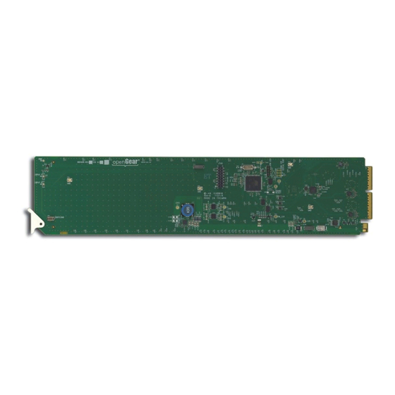
Page 22: Card Overview
Figure 3.1 Card-edge Controls 1. Bootload Button This button is used for factory service in the unlikely event of a complete card failure. Do not use this button unless advised by Ross Technical Support. For More Information on... • the Bootload process, refer to the section “Bootload Button” on page 6-2. -
Page 23: Monitoring Features
When lit red or flashing red, this LED indicates the card is not operational. Re-seat card in frame, check the rear module type and connections, or call Ross Video Technical Support. When unlit, this LED indicates there is no power to the card. -
Page 24: Using Dashboard
Using DashBoard Before proceeding, ensure that the DashBoard client is installed on a PC connected to your facility network. The DashBoard software and user manual area available from the Ross Video website. For More Information on... • installing DashBoard, refer to the DashBoard User Manual. -
Page 25: Configuring The Dea-8805
Configuring the DEA-8805 This section briefly outlines how to configure the DEA-8805 using the options available in DashBoard. Configuring the Equalizer for a Channel You can choose to enable or bypass the equalizer on each channel. The equalizer enables the card to compensate for noise and signal losses inherent in long coaxial cable runs. -
Page 26: Loss Of Input
Loss of Input When enabled, this feature will indicate an alarm condition (red) in the Channel Status field of the Signal tab. This occurs if the DEA-8805 does not detect a valid input signal for that channel. To verify which BNC to troubleshoot, refer to the rear module labeling or the Input BNC field in the Setup tab. -
Page 27: Dashboard Menus
DashBoard Menus In This Chapter This chapter briefly summarizes the menus, items, and parameters available from DashBoard for your card. Default parameters are noted with an asterisk (*). The following topics are discussed: • Status Tabs • Setup Tab • Alarms Tab Operating Tip —... -
Page 28: Status Tabs
Status Tabs This section summarizes the read-only information displayed in the Status tabs. The fields in the Signal tab vary in severity from green (valid), yellow (caution), to red (alarm). DashBoard reports the most severe alarm for a single field. Alarm colors are noted within the tables as text set in brackets next to the menu parameter name. -
Page 29: Hardware Tab
Tab Title Item Parameters Description Product DEA-8805 Displays the card model Supplier Ross Video Ltd. Indicates the manufacturer of your card Board Rev Indicates the version of the PCB Board S/N ###### Indicates the card serial number Product Indicates the installed rear module... -
Page 30: Setup Tab
Setup Tab Table 4.4 summarizes the Setup options available in DashBoard. Table 4.4 Setup Menu Items Menu Title Item Parameters Description Indicates the BNC on the rear module that # (read-only) is assigned as the input source for the specified channel Input BNC Indicates that no BNCs are currently used as inputs for the channel... -
Page 31: Alarms Tab
Alarms Tab Table 4.5 summarizes the Alarms options available in DashBoard. Table 4.5 Alarm Enables Menu Items Menu Title Item Parameters Description The Status fields in the Signal tab reports Selected* the loss of the specified input as an error/alarm Alarm on Loss of Input Channel # The Status fields in the Signal tab reports... - Page 32 4–6 • DashBoard Menus DEA-8805 User Manual (Iss. 04)
-
Page 33: Specifications
Specifications In This Chapter This chapter includes the technical specifications for the DEA-8805. Note that specifications are subject to change without notice. The following topics are discussed: • Technical Specifications DEA-8805 User Manual (Iss. 04) Specifications • 5–1... -
Page 34: Technical Specifications
Technical Specifications This section lists the technical specifications for the DEA-8805. Table 5.1 Technical Specifications Category Parameter Specification Supported Rear Modules 8320AR-300, 8320AR-302 Rear Modules Number of Inputs 19.39Mbps, 38.78Mbps, SMPTE 310 270Mbps, 525/625 Component, SMPTE 259M Data Rates and SMPTE Standards 270Mbps, DVB-ASI Accommodated 1.485Gbps Component, SMPTE 292M... - Page 35 Service Information In This Chapter This chapter contains the following sections: • Troubleshooting Checklist • Warranty and Repair Policy DEA-8805 User Manual (Iss. 04) Service Information • 6–1...
- Page 36 Bootload Button In the unlikely event of a complete card failure, you may be instructed by a Ross Technical Support specialist to perform a complete software reload on the card.
- Page 37 In the event that your DEA-8805 proves to be defective in any way during this warranty period, Ross Video Limited reserves the right to repair or replace this piece of equipment with a unit of equal or superior performance characteristics.
- Page 38 Contact Us Contact our friendly and professional support representatives for the following: • Name and address of your local dealer • Product information and pricing • Technical support • Upcoming trade show information Telephone: +1 613 • 652 • 4886 Technical After Hours Emergency: +1 613 •...
Need help?
Do you have a question about the OpenGear DEA-8805 and is the answer not in the manual?
Questions and answers