Table of Contents
Advertisement
Quick Links
Advertisement
Table of Contents
Troubleshooting

Related Manuals for Ross openGear HDC-8223A


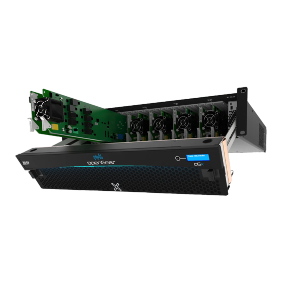
Summary of Contents for Ross openGear HDC-8223A
- Page 1 HDC-8223A(-S) User Guide...
- Page 2 Ross has become well known for the Ross Video Code of Ethics. It guides our interactions and empowers our employees. I hope you enjoy reading it below. If anything at all with your Ross experience does not live up to your expectations be sure to reach out to us at solutions@rossvideo.com.
- Page 3 Ross Video. While every precaution has been taken in the preparation of this document, Ross Video assumes no responsibility for errors or omissions. Neither is any liability assumed for damages resulting from the use of the information contained herein.
- Page 4 Notice — Changes or modifications to this equipment not expressly approved by Ross Video Ltd. could void the user’s authority to operate this equipment. Canada This Class “A”...
- Page 5 The crossed-out wheeled bin symbol invites you to use these systems. If you need more information on the collection, reuse, and recycling systems, please contact your local or regional waste administration. You can also contact Ross Video for more information on the environmental performances of our products.
-
Page 7: Table Of Contents
Contents Introduction Related Publications ..........................11 Documentation Conventions ........................11 Interface Elements ..........................11 User Entered Text ..........................11 Referenced Guides ..........................12 Menu Sequences ........................... 12 Important Instructions .......................... 12 Contacting Technical Support ......................... 12 Before You Begin Overview ..............................13 Video Subsystem Overview ........................ - Page 8 Function Sub-menu/Parameter Sub-menu Overview ............... 27 Using DashBoard ............................27 Checking Card Information ........................28 Operation Ancillary Data Line Number Locations and Ranges ................29 Timecode ..............................30 Examples Cases A, B ..........................30 Example Case C ............................31 Closed Captioning ............................ 31 Troubleshooting ............................
- Page 9 DashBoard Status/Error Indicators and Displays ................. 67 Basic Troubleshooting Checks ........................ 68 Processing Error Troubleshooting ......................69 Troubleshooting Network/Remote Control Errors ................69 Firmware Upgrades Before You Begin ............................71 Firmware Upgrade Controls ........................71 Technical Specifications SDI Inputs Specifications ......................... 73 Post-Processor Serial Digital Video Outputs ..................
- Page 10 iv • Contents HDC-8223A(-S) User Guide (v4.0)
-
Page 11: Introduction
• “Service Information” provides information on the warranty and repair policy for your card. • “Glossary” provides a list of terms used throughout this guide. Related Publications It is recommended to consult the following Ross documentation before installing and configuring your HDC-8223A(-S): • DashBoard User Manual, Ross Part Number: 8351DR-004 •... -
Page 12: Referenced Guides
Gateway for your device. Contacting Technical Support At Ross Video, we take pride in the quality of our products, but if problems occur, help is as close as the nearest telephone. Our 24-hour Hot Line service ensures you have access to technical expertise around the clock. -
Page 13: Before You Begin
Before You Begin The HDC-8223A(-S) is a monitoring quality down-converter that also offers optional audio support. The down-converted SDI and analog composite signals are selected through four, 2:1 crosspoints allowing any combination of SD-SDI or analog composite (CVBS) outputs on the four card processed video outputs. -
Page 14: Scaler Function
Scaler Function The scaler function provides down-conversion to SD from multiple standard SD, and 3G/HD video formats and multiple frame rates, with auto-format detect/down-conversion of SMPTE 424M/292M/259M formats. Color framing is preserved on CVBS outputs for all conversions. The scaler function also provides aspect ratio conversion that provides a choice from several standard aspect ratios. -
Page 15: Closed Captioning Processor
Closed Captioning Processor This function provides support for closed captioning setup. When receiving HD-SDI, both CEA 608 and CEA 708 are supported, with CEA 608 and CEA 708 (containing CEA 608 packets) converted to line 21 closed captioning on outputs down-converted to SD. Ancillary Data Processor This function provides VANC/HANC ancillary data “bridging”... -
Page 16: Audio Down Mix Function
The router function provides the following audio outputs: • 16 channels of embedded audio on SDI processed outputs • 4 channels of balanced analog audio on four 3-wire balanced analog audio outputs Output audio crosspoints allow any of these sources to be routed to any of the 16 embedded output channels or the four analog audio outputs. -
Page 17: Workflow With The R2-8223A Rear Module
Workflow with the R2-8223A Rear Module Figure 3 outlines the workflow of the HDC-8223A(-S) when installed with the R2-8223A full rear module. RCLK Copy 1 RCLK Copy 2 RCLK Copy 3 RCLK Copy 4 SDI/CVBS OUT 1 SDI SERIALIZER / 4 x DA SDI/CVBS OUT 2 SDI/CVBS OUT 3 SD VIDEO DAC... -
Page 18: Workflow With The R2C-8223A Rear Module
Workflow with the R2C-8223A Rear Module Figure 4 outlines the workflow of the HDC-8223A(-S) when installed with the R2C-8223A full rear module. RCLK Copy 1 RCLK Copy 2 SDI SERIALIZER / 4 x DA SDI/CVBS OUT 1 SDI/CVBS OUT 2 SD VIDEO DAC / 4 x DA VIDEO... -
Page 19: Hardware Overview
Hardware Overview This chapter provides a general overview of the user controls available on your HDC-8223A. Control and Monitoring Features This section describes the card-edge status LEDs and display. These LEDs and the display show status and error conditions relating to the card itself and remote (network) communications (where applicable). - Page 20 Table 1 provides basic LED descriptions. Table 1 LEDs on the HDC-8223A Color Display and Description Flashing Blue When flashing, this LED indicates that the HDC-8223A is receiving control message from DashBoard. Blue When lit, this LED indicates that the HDC-8223A is receiving valid reference.
-
Page 21: Physical Installation
Unpacking Unpack each card you received from the shipping container and ensure that all items are included. If any items are missing or damaged, contact your sales representative or Ross Video directly. Installing a Rear Module The R2-8223A Full Rear Module or the R2C-8223A Full Rear Module can be used. If the Rear Module is already installed, proceed to “Installing the Card”. -
Page 22: Installing The Card
Installing the Card This section outlines how to install the card in an openGear frame. If the card is to be installed in any compatible frame other than a Ross Video product, refer to the frame manufacturer’s manual for specific instructions. -
Page 23: R2-8223A Cabling Overview
R2-8223A Cabling Overview Each rear module occupies two slots and accommodates one card. This rear module provides two HD/SD-SDI coaxial inputs, four output copies of the re-clocked inputs, and four processed coaxial outputs (can be configured as analog composite or SD-SDI). (Figure 6) SDI In A SDI In B RCLK Copy... -
Page 24: Audio Cabling
Audio Cabling The R2C-8223A rear module also provides 3-pin audio terminal blocks with removable connectors. Each block has locations for the positive, negative, and grounded wires of a balanced audio cable. To cable the analog audio connections 1. Insert an analog audio wire to the designated polarity slots on the connector of the rear module. -
Page 25: Cabling
Cabling This chapter provides information for connecting the input and output cables to the installed rear modules on the openGear frames. The input is internally terminated with 75ohms. It is not necessary to terminate unused outputs. The cabling is the same regardless of the card model. R2-8223A Cabling Overview Each rear module occupies two slots and accommodates one card. -
Page 26: Audio Cabling
Audio Cabling The R2C-8223A rear module also provides 3-pin audio terminal blocks with removable connectors. Each block has locations for the positive, negative, and grounded wires of a balanced audio cable. To cable the analog audio connections 1. Insert an analog audio wire to the designated polarity slots on the connector of the rear module. -
Page 27: Using Dashboard
Figure 10 Function Sub-menu/Parameter Sub-menu Overview — HDC-8223A Using DashBoard Before proceeding, ensure that the DashBoard Control System is installed on a PC connected to your facility network. The DashBoard software and user manual are available from the Ross Video website. To launch DashBoard 1. -
Page 28: Checking Card Information
To access a card in DashBoard 1. From the Tree View, expand the node for the openGear frame your cards are installed in. A list of cards installed in the frame is now displayed. In the example below, the node for Frame 1 is expanded to show a list including an HDC-8223A. -
Page 29: Operation
Operation This chapter provides instructions for configuring the HDC-8223A(-S). Ancillary Data Line Number Locations and Ranges Table 2 lists typical default output video VANC line number locations for various ancillary data items that may be passed or handled by the HDC-8223A(-S). Table 2 Typical Ancillary Data Line Number Locations/Ranges Default Line No. -
Page 30: Timecode
Figure 12 shows an example of corrected VANC allocation within an HD-SDI stream. ATC_VITC = 9/8 Conflict between ATC_VITC = 9/8 CC = 10 ATC_VITC on line 9/8 and AFD (now on line 18) CC = 10 Dolby® Metadata = 13 resolved AFD = 18 Dolby®... -
Page 31: Example Case C
REFERENCE VITC DETECT/EXTRACT 720p SDI with ATC_LTC PRIORITY / VITC WAVEFORM SELECT ATC_LTC TIMECODE DETECT/EXTRACT PROC / EMBED SDI ATC_VITC DETECT/EXTRACT ATC_VITC TIMECODE PROC / EMBED BUFFER / FORMAT SDI VITC Waveform DETECT/EXTRACT FREE RUN (INTERNAL COUNT) 525i SDI with ATC_VITC with VITC Waveform INSERT CONTROL LINE NUMBER CONTROL... -
Page 32: Troubleshooting
For More Information on... • the menus and parameters available for the closed captioning feature, refer to “Closed Captioning Tab”. Troubleshooting The message “ ” is displayed due to the items described below. The Captioning Rejected Due to closed captioning function assesses , and cdp_identifier cdp_frame_rate... -
Page 33: Output Audio Routing Controls
Overlay markers using this function are for setup only. When enabled, these markers are embedded in the output video and will appear in the image. Use this function only on preview video and not on-air video. Make certain any overlay tools are turned off when no longer needed. Output Audio Routing Controls The Output Audio Routing feature includes the following options in DashBoard: •... -
Page 34: Adding An Overlay
The -0 dB setting applies no ratiometric reduction. Surround-channel content is restored with no attenuation, making Lo and Ro content more predominate in the overall mix. The maximum attenuation setting (-80dB) applies a -80dB ratiometric reduction of surround-channel content. Surround-channel content is restored at a -80dB ratio relative to overall level, making surround-channel content less predominate in the overall mix. -
Page 35: Adding A Timecode Overlay
3. From the Overlay menu, select one of the following: • Always enabled — The text overlay always displays on the output. • Enabled on loss of video — The text overlay only displays when the card detects a loss of the input video signal. - Page 36 3. From the Overlay menu, select one of the following: • Always enabled — The timecode overlay always displays on the output. • Enabled on loss of video — The timecode overlay only displays when the card detects a loss of the input video signal.
-
Page 37: Scaler
Scaler The Scaler feature provides aspect ratio controls including Horizontal and Vertical pan controls. Each Scaler control is fully described in “Scaler Tab”. Figure 21 H Pan Control Figure 22 V Pan Control HDC-8223A(-S) User Guide (v4.0) Operation • 37... - Page 38 38 • Operation HDC-8223A(-S) User Guide (v4.0)
-
Page 39: Dashboard Menus
DashBoard Menus This chapter briefly summarizes the menus, items, and parameters available from DashBoard for your card. Default parameters are noted with an asterisk (*). Status Tabs This section summarizes the read-only information displayed in the Status tabs. The fields in the Status tabs can vary in severity from green (valid), yellow (caution), to red (alarm). -
Page 40: Product Info Tab
This field reports HDC-8223A even if the Frame Sync option is installed Product Options Indicates which licensed features are installed on the HDC-8223A(-S) Supplier Ross Video Ltd. Indicates the provider of the HDC-8223A(-S) Revision #.##.# Indicates the software version Build Date... - Page 41 Table 6 Timecode Tab Items Item Parameters Description Source Priority # Selects the priority assigned to each of the four supported external formats, and internal Free Run in the event the preferred source is unavailable. Set Incoming ATC Packet Removal Control to Enabled if Free-Run timecode is to be used.
- Page 42 Table 6 Timecode Tab Items Item Parameters Description SD VITC Waveform For SD output, enables or disables SD VITC Output # Line waveform timecode insertion into the output Number video, and selects the VITC1 and VITC2 line numbers (6-22) where the VITC waveform is inserted If only one output line is to be used, set both controls for the same line number.
-
Page 43: Reticules Tabs
Table 6 Timecode Tab Items Item Parameters Description Incoming ATC Enabled Enables or disables removal of existing input Packet Removal video ATC timecode packets from the output. Disabled This allows removal of undesired existing timecodes from the output, resulting in a “clean slate”... -
Page 44: Reticules Advanced Tab
Table 7 Reticules Basic Tab Items Item Parameters Description SDI Out Reticule Disable Insertion of all reticules or other markers is disabled Enable Provides independent master enable/disable for card SDI outputs. Any combination of reticules or other markers described below can be inserted. Analog Out Reticule Disable Insertion of all reticules or other markers is... -
Page 45: Input Video Tab
Table 8 Reticules Advanced Tab Items Item Parameters Description Graticule Disable Disables user graticule insertion Enable Enables user graticule insertion Graticule Height 0-100 Controls height of insertion; percentage of 4:3 outputted image area Graticule Width 0-100 Controls width of insertion; percentage of 4:3 outputted image area Center Cross Disable... -
Page 46: Output Video Tab
Table 9 Input Video Tab Items Item Parameters Description SDI A Allow forced manual selection of Input Video Source correspondingly SDI IN A or SDI IN B SDI B Failover A to B Sets main path preference of SDI IN A: •... -
Page 47: Output Routing Tab
Output Routing Tab The Output Routing tab allows selection of each of the four video output coaxial connectors as SD-SDI or CVBS output mode. Table 10 summarizes the options available in the Output Routing tab. Table 10 Output Routing Tab Items Item Parameters Description... - Page 48 Table 12 Scaler Tab Items Item Parameters Description Input Video Displays signal format/status sent to scaler (as a (read-only) function of the Input Video source setting) Unlocked An invalid or unavailable signal is detected Output Video Displays output signal format/status (read-only) Unlocked An invalid or unavailable signal is detected...
-
Page 49: Framesync Tab
Framesync Tab The Framesync tab is only available when using the HDC-8223A-S. When displayed, this tab provides video frame sync/delay offset control and output control/loss of program failover selection controls. The frame sync provides H and V timing adjustments that affect both the CVBS and the down-converted SDI outputs simultaneously. - Page 50 Table 13 Framesync Tab Items Item Parameters Description Output Mode Input Video Card outputs program video (or loss of signal selection in the On Loss of Video menu) Flat Field Card outputs flat field Freeze Card outputs last frame having valid SAV and EAV codes Test Pattern Card outputs a test pattern.
-
Page 51: Closed Captioning Tab
Table 13 Framesync Tab Items Item Parameters Description Frame Delay When Framesync is enabled, specifies the smallest amount of latency delay (frames held in buffer) allowed by the frame sync. The frame sync will not output a frame unless the specified number of frames are captured in the buffer. -
Page 52: Video Proc Tab
Table 14 Closed Captioning Tab Items Item Parameters Description Incoming Packet Disabled Allows removal of closed captioning packets Removal and regeneration of line 21 closed captioning. Enabled The Regenerate Source Select control on this card should only be set to Program Input since this model does not support a second analog video input. -
Page 53: Output Audio Routing/Controls Tab
Output Audio Routing/Controls Tab This section summarizes the options in the Output Audio Routing/Controls sub-tabs. Embedded Output Tab Table 16 summarizes the options in the Embedded Output sub-tab. Table 16 Embedded Output Tab Items Item Parameters Description Group # Enabled Allows the specified embedded audio group on card program video output to accommodate some legacy downstream systems that may not... -
Page 54: Audio Delay Tab
Table 17 Downmixer Tab Items Item Parameters Description Left Channel Input Silence Left Channel Input thru Right Surround Channel Input select the five embedded source channels Audio Bus Ch # to be used for the downmix. Right Channel Input Silence Downmix channels Downmixer L and Downmixer R are available as sources for Audio Bus Ch #... -
Page 55: Analog Output Tab
For each Flex Mix input channel, its source should be considered and appropriately set. Unused input channels should be set to Silence. Table 19 summarizes the options in the Flex Mix sub-tab. Table 19 Flex Mix Tab Items Item Parameters Description Flex Mix Input #... -
Page 56: Afd/Wss/Vi Sub-Tab
AFD/WSS/VI Sub-tab Table 21 summarizes the options in the AFD/WSS/VI sub-tab. Table 21 AFD/WSS/VI Tab Items Item Parameters Description Inputs Input > AFD Status Detected Displays the current status and contents of the (read-only) three supported ARC formats. If a format is received, the current formatting code and description is displayed. - Page 57 Table 21 AFD/WSS/VI Tab Items Item Parameters Description AFD Output Enabled Individual ARC format input controls allow accepting the received ARC formats and inserts AFD packet on output, and allows changing the line number. Disable Turns off AFD format on the output Follow Input Line Inserts AFD packet on same line as received AFD line number (where applicable)
-
Page 58: Afd Map Sub-Tab
Table 22 AFD Coding Matrix Input Output Description Description 0010 4x3 Letterbox 16x9 Top 0010 4x3 Letterbox 16x9 Top 0011 4x3 Letterbox 14x9 Top 0011 4x3 Letterbox 14x9 Top 0100 4x3 Letterbox 16x9 Center 0100 4x3 Letterbox 16x9 Center 0101 Undefined 0110 0111... -
Page 59: Character Burner Tab
Click this button to apply the changes made to the Display Text field and any options in the tab Character Size Specifies the font size of the text overlay. Ross Video recommends selecting a size of 40 or greater. Text Justification... -
Page 60: Timecode Tab
Table 23 Ident Tab Items Item Parameters Description Custom # Selecting a custom option enables you to Position Mode customize the position of the overlay using the applicable sliders Selecting a non-custom option specifies where the anchor point of the overlay is positioned 0 to 100 When the Position Mode is set to Custom, this Horizontal Position... - Page 61 Character Size Specifies the font size of the timecode overlay. Ross Video recommends selecting a size of 40 or greater. Text Justification Specifies how to align the text in the overlay...
-
Page 62: Ancillary Data Processing Tab
Table 24 Timecode Tab Items Item Parameters Description Text Box Size Auto The overlay automatically re-sizes to fit the timecode data Custom Enables you to customize the size of the overlay box using the applicable sliders Text Box Width 0 to 100 When the Text Box Size is set to Custom, this slider adjusts the horizontal margins of the text Text Box Height... -
Page 63: Presets Tab
Presets Tab The Presets tab allows user control settings to be saved in a Preset and then loaded (recalled) as desired. There is also the option to configure a one-button restore of factory default settings. Table 26 summarizes the options available in the Presets tab. Table 26 Presets Tab Items Item Parameters... -
Page 64: Notes On Uploading Presets
Table 26 Presets Tab Items Item Parameters Description Load Factory Confirm Allows recalling the factory default preset. Defaults When this button is selected, the changes captured in the preset are immediately applied. Note: This feature functions with no masking. The Preset Layer Select controls have no effect on this control and will reset all layers to factory default. -
Page 65: User Log Tab
Firmware Memory Test Restore From SD Confirm Do not configure these settings without the Card guidance of Ross Technical Support FPGA Memory Test Test Memory Test Status (read-only) User Log Tab Table 28 summarizes the options in the User Log tab. - Page 66 Table 28 User Log Tab Items Item Parameters Description Download Log File *.tar.gz Allows a card operational log file to be saved to a host computer. This log file can be useful in Save case of a card error or in the case of an operational error or condition.
-
Page 67: Troubleshooting
Troubleshooting This chapter provides general troubleshooting information and specific symptom/corrective action for the HDC-8223A(-S). The HDC-8223A(-S) card requires no periodic maintenance in its normal operation; if any error indication occurs, use this chapter to correct the condition. Error and Failure Indicator Overview The HDC-8223A(-S) card itself and its DashBoard menus (to varying degrees) provide error and failure indications. -
Page 68: Basic Troubleshooting Checks
Table 29 DashBoard Status Indicators Icons and Displays Indicator Icon or Display Error Description Yellow indicator icon in the HDC-8223A Card Info pane shows error alert, along with cause for alert. In this example, the HDC-8223A is not receiving an enabled framesync source. -
Page 69: Processing Error Troubleshooting
Troubleshooting Network/Remote Control Errors Should any problem arise with this product that was not solved by the information in this section, contact Ross Video Technical Support. Refer to “Contacting Technical Support”. HDC-8223A(-S) User Guide (v4.0) Troubleshooting • 69... - Page 70 70 • Troubleshooting HDC-8223A(-S) User Guide (v4.0)
-
Page 71: Firmware Upgrades
Firmware Upgrades This chapter outlines the firmware upgrade controls for your HDC-8223A(-S). Before You Begin Keep the following in mind before beginning to upgrade the firmware: • You cannot downgrade a card from version 1.75 to an earlier version. • Version 1.75 is not DataSafe compatible with prior versions of the firmware. Saved configurations from versions prior to 1.75 cannot be loaded onto cards running version 1.75. - Page 72 72 • Firmware Upgrades HDC-8223A(-S) User Guide (v4.0)
-
Page 73: Technical Specifications
Technical Specifications This chapter provides the technical specification information for the HDC-8223A(-S). Note that specifications are subject to change without notice. SDI Inputs Specifications Table 32 Technical Specifications — SDI Inputs Item Specifications Number of Inputs 2 with manual select or failover Data Rates Supported SMPTE 424M, 259M, SMPTE 292M Impedance... -
Page 74: Analog Composite Video Outputs
Analog Composite Video Outputs Table 35 Technical Specifications — Analog Composite Video Outputs Item Specifications Number of Outputs Up to four SD analog CVBS via selector mux Impedance 75 Return Loss -30dB to 10MHz Frequency Response NTSC: 4.8MHz +/- 0.2dB PAL: 5.8MHz +/- 0.2dB S/N Ratio 50dB... -
Page 75: Service Information
Bootload Button In the unlikely event of a complete card failure, you may be instructed by a Ross Technical Support specialist to perform a complete software reload on the HDC-8223A. To reload the software on a HDC-8223A 1. - Page 76 HDC-8223A. If required, a temporary replacement frame will be made available at a nominal charge. Any shipping costs incurred will be the responsibility of you, the customer. All products shipped to you from Ross Video Limited will be shipped collect.
-
Page 77: Glossary
Glossary The following terms are used throughout this guide: Active image — the portion of the video picture area (production aperture) that is being utilized for output content. Active image excludes letterbox bars and pillarbox bars. Card — openGear terminal devices within openGear frames, including all components and switches. - Page 78 78 • Glossary HDC-8223A(-S) User Guide (v4.0)
Need help?
Do you have a question about the openGear HDC-8223A and is the answer not in the manual?
Questions and answers