
Subscribe to Our Youtube Channel
Related Manuals for BETCO XT3 27


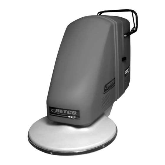
Summary of Contents for BETCO XT3 27
- Page 1 E12603-00 XT3 2 2 7 7 27” Battery Burnisher Operator’s Manual Parts Schematic ©2007 Betco Corporation. All Rights Reserved. 1001 Brown Avenue • Toledo, Ohio 43607-0127 • 888-GO-BETCO • www.betco.com...
-
Page 2: Table Of Contents
Table of Contents Page Description Table of Contents Safety Instructions - Very Important - Must Read Product Specifications Procedures for Loading, Transporting, and Unloading Machine Operating Instructions Battery Charging Battery Maintenance Battery Charger Operation Battery Charger Settings Battery Discharge Indicator (BDI) & Hour Meter Pad Changing Instructions Machine Balancing Set Up Belt Tensioning... - Page 3 SAFETY INSTRUCTIONS Hazard Level Explanation or Description of Hazard Level Failure to follow safety instructions labeled could result in severe injury or death to the machine operator or others. could result in injury to the machine operator or others. Also, machine or property damage could occur.
- Page 4 SAFETY INSTRUCTIONS Battery acid is dangerous. Wear eye and face protection, hand protection, and body protection when working on and around batteries. If you get acid on your skin, wash off immediately. If you get acid on your clothing, remove clothing and wash any skin that was in contact with the clothing.
-
Page 5: Product Specifications
XT3 - 27 Product Specifications Burnish path: 27” Pad size: 27” Motor: Maintenance Free, brushless, rated at 5 hp. Motor controller: Monitors and maintains consistent pad speed and torque Motor speed: 2000 rpm Pad pressure: Approx. 30 lbs. Pad driver: Flexible, Flex Lock III Center lock: Threaded, for easy installation... - Page 6 Procedures for Loading, Transporting, and Unloading Battery Burnisher DANGER: The machine is very heavy, so be very careful when loading, transporting, and unloading the machine. Use at least two people to load or unload the machine. • Loading Procedure Using a Ramp a) It is not recommended that the battery burnisher be loaded using a ramp with an incline of more than 7 degrees.
-
Page 7: Operating Instructions
OPERATING INSTRUCTIONS TO START BUFFING: SAFETY LEVER # 1 - TURN ON KEY SWITCH # 2 - TURN ON ROCKER SWITCH KEY SWITCH # 3 - DEPRESS SAFETY HANDLE AND BEGIN BUFFING ROCKER SWITCH TO END BUFFING: # 1 - RELEASE SAFETY HANDLE # 2 - TURN OFF ROCKER SWITCH # 3 - TURN OFF KEY SWITCH AFTER EACH USE:... -
Page 8: Battery Charging
BATTERY CHARGING REFER TO NEXT THREE PAGES FOR BATTERY CHARGER OPERATION AND BATTERY MAINTENANCE • Become familiar with and follow the instructions issued by the charger manufacturer. • Batteries should be charged after each period of use. Lead acid batteries do not develop a memory and need not be fully discharged before recharging. - Page 9 figure 2 DO NOT OVERFILL. DO NOT FILL ABOVE THE BOTTOM OF THE TUBE THAT EXTENDS INTO BATTERY. KEEP ABOUT 1/4" BELOW BOTTOM OF TUBE. WATER LEVEL ADD DISTILLED WATER, AS NEEDED, IN THIS SO THAT ELECTROLYTE LEVEL WATER CELL IS IS ABOUT 1/2"...
-
Page 10: Battery Charger Operation
BATTERY CHARGER OPERATION OPERATION • PLUG THE CORD FROM THE CHARGER INTO A 110 VOLT OUTLET • Batteries should now start charging. • A test is run on the battery voltage to decide if the charging process should be started or not. If the battery is not connected to the battery charger, the display will show the word “bat”. - Page 11 HOW TO SET THE CHARGER FOR DIFFERENT SIZES AND TYPES OF BATTERIES THE INFORMATION THAT FOLLOWS IS PROVIDED SHOULD YOU EVER CHANGE THE TYPE OR SIZE OF BATTERIES IN YOUR MACHINE. CONSULT WITH THE EQUIPMENT MANUFACTURER BEFORE YOU MAKE ANY CHANGES TO THE CHARGER SETTINGS.
-
Page 12: Battery Discharge Indicator (Bdi) & Hour Meter
BATTERY DISCHARGE INDICATOR (BDI) AND HOUR METER Connector pin configuration (B) 1: hour meter input - 2: key + 3: relay + 4: relay – 1 2 3 4 5: battery – 6: not used 5 6 7 8 7: not used 8: battery + BACK FRONT... -
Page 13: Pad Changing Instructions
PAD CHANGING INSTRUCTIONS TILT MACHINE BACK AND REMOVE FRONT COVER DO NOT TILT MACHINE ON ITS SIDE USE 3/4" OPEN END WRENCH TO SECURE SHAFT AND SPIN PAD DRIVER OFF SHAFT BY HAND DETAIL A SCALE 1 : 6 CENTER THE PAD ON PAD HOLDER AND TIGHTEN CENTER LOCK USE THE HI-SHINE LIGHT BURNISH PAD SPIN PAD DRIVER BACK ONTO SHAFT... - Page 14 BALANCING INSTRUCTIONS TO ACHIEVE PROPER MACHINE BALANCE SHIFT SHIMS FROM FRONT TO BACK OR BACK TO FRONT OF BATTERIES For best operation and maximum battery life, the XTG3 battery burnisher must have the correct pad pressure. The burnisher should require only minor adjustments to the balance. Only the battery shims should be adjusted.
- Page 15 BETCO CORP. 6/22/07 Page 17 XT3 BATTERY BURNISHER...
- Page 16 CPC button in and pulling the male Quick Coupler out. Put the dust cover back on the battery's male Quick Coupler. Store hose out of traffic area when not in use. Connect Quick Coupler to connector on machine BETCO CORP. 6/22/07 Page 18 XT3 BATTERY BURNISHER...
- Page 17 WATERING SYSTEM INSTRUCTIONS FOR 6 VOLT WET CELL BATTERIES PLEASE REFER TO SEPARATE “PRO-FILL ON-BOARD WATERING SYSTEM” MANUAL FOR DETAILED INFORMATION PURGING INSTRUCTIONS BETCO CORP. 6/22/07 Page 19 XT3 BATTERY BURNISHER...
-
Page 18: Covers & Handle Parts
Covers & Handle Parts E11565 E12215 E12221 E11553 E11122 E12639 E12638 E10259 E12197 E12242 E10135 E83629 E81066 E12632 E12626 E12641 E12633 E88152 E11833 E12676 E12633 E12640 E12676 E11834 E12625 E11834 E88150 E11833 E88153 E12447 E12654 E88151 E83629 E81066... - Page 19 Covers & Handle Parts PART Description QTY. NUMBER E10135 Washer, 3/8" USS, Zinc E10259 Plug, 1" Tube E11122 Screw 1/4" x .500 Pan Head Phillips E11407 Screw, 5/16"-18 x 3.250 Eyebolt with Nut, Zinc E11553 Lanyard 3/64" x 6" XT Safety Switch E11565 Spring, Extension 0.080 Wire, 1/2"...
-
Page 20: Frame & Deck Parts
Frame & Deck Parts E12204 E11293 - Dust Skirt 28" E11833 E12636 E12584 is supplied with the machine. E81087 After removing the 5/16" eye bolt (E11407) insert it into the hole, E12643 use a hammer to seat. E10135 E10122 E12661 E81087 E81713 E10118... - Page 21 Frame & Deck Parts PART Description QTY. NUMBER E10118 Rivet AAP64 E10122 Screw, 1/4"-20 x 1.000 Hex Head, Grade 5, Zinc E10135 Washer, 3/8" USS, Zinc E10141 Nut, 5/16"-18, Slim, Nylon Lock, Grade 5, Zinc E10202 Rivet, 3/16" OD x 0.700" L with 0.600" Head E10705 Bumper, Red (21"...
-
Page 22: Belt Drive Parts
Belt Drive Parts 21" & 28" Deck Shimming: E10116 Place 2 of the E83269 & 1 of the E12447 between E12709 & aluminum deck at this bolt location. E10117 E83629 E81066 E12447 E10135 E10459 E12709 E11289 E12459 E12401 -- 21" Deck E12663 E10428 -- 28"... - Page 23 Belt Drive Parts PART Description QTY. NUMBER E10107 Belt, BX40 E10116 Screw, 7/16"-14 x 1.250 Hex Head, Grade 5, Zinc E10117 Washer, 7/16" Split Lock, Zinc E10135 Washer, 3/8" USS, Zinc E10459 Belt Tensioner E10725 Screw, 1/4"-20 x 1.500 Hex Head, Grade 5, Zinc E11135 Washer, 3/4"...
-
Page 24: Pad Driver Parts
Pad Driver Parts EP50028 -- 21" Pad Drive Assembly EP50040 -- 27" Pad Drive Assembly E10112 E81067 E10586 E12444 E10250 -- 21" Pad Driver E10252 -- 27" Pad Driver E81063 E12517 2 Piece Set E10850 84621 -- 24" Pad 84627 -- 27" Pad E12517 2 Piece Set... - Page 25 Pad Driver Parts PART Description QTY. NUMBER 84621 Pad, 21" Hi-Shine Light Burnish Pad, 5/Case 84627 Pad, 27" Hi-Shine Light Burnish Pad, 5/Case E10112 Screw, 5/16"-18 x 1.250 Hex Head Grade 5, Zinc E10250 21" Pad Driver E10252 27" Pad Driver E10586 3/4"...
-
Page 26: Battery & Electrical Parts
Battery & Electrical Parts E12631 E12691 E12613 E12690 E12542 E12543 E11563 E12630 E12646 E11529 E12636 E88149 E12629 E12642 E12219 E11834 E12568 E88853 E11096 E12660 E12263 E10137 E12624 E12621 E12628 E11833 E11353 E11834 E12643 E12565 E10878 E12564 E11623... - Page 27 Battery & Electrical Parts PART Description NUMBER E10137 Clamp, Tube 1/2" (COV-0909) E10878 Anderson Plug, Grey E11096 Nut, #10 - 32, Black E11353 Tube Clamp 3/4" (COV-1309) E11407 Screw, 5/16"-18 x 3.250 Eyebolt with Nut, Zinc E11529 SWITCH, ROCKER E11563 Battery, 6V, 225AH, Wet Cell E11623 Screw 1/4"...
- Page 28 XT3-27 BATTERY CONNECTIONS CONNECTIONS FOR BOTTOM BATTERIES SHOWN RED TREMINAL PROTECTORS ARE ON POSITIVE TERMINALS BLACK TERMINAL PROTECTORS ARE ON NEGATIVE TERMINALS ITEM NO. PART NO. QTY. DESCRIPTION E012568 WIRE, BATTERY CABLE, 4 GA, RED, 7.75" E012542 TERMINAL PROTECTOR, STRAIGHT, BLACK E012543 TERMINAL PROTECTOR, STRAIGHT, RED E011563...
- Page 29 XT3-27 WATERING WITH STANDARD BATTERIES PRO-FILL WATERING SYSTEM - PART # E012613...
-
Page 30: Electrical Layout
Electrical Layout E011835 FUSE HOLDER E081785 E011106 FUSE 10A E088635 WIRE HARNESS (INCLUDES ALL CONTROL WIRING) E011139 E012562 E081785 E012562 E012669 E012563... -
Page 31: Wiring Ladder Diagram
Wiring Ladder Diagram CHARGER K - KEY SWITCH R - ROCKER SWITCH 5 15 17,26,29 S - SAFETY SWITCH F - FUSE C- SOLENOID MOTOR B - BLUE MOTOR BL - BLACK CONTROL Y - YELLOW R - RED 18 4 1 2,24 G - GREEN BATTERY... - Page 32 TROUBLE-SHOOTING PROBLEM CAUSE POSSIBLE SOLUTION No sign of power. No on (a) Bad connection (a) Check all connections. lamp, no BDI readout. (b) Bad connection to BDI (b) Make sure connector is fully pushed into (c) On-board charger is BDI. plugged in (c) Disconnect charger from wall outlet.
-
Page 34: Warranty
Betco authorized Service Distributor. If the original part is returned within the warranty policy period from date of delivery for inspection by Betco and is found to be defective, the owner will be credited for the cost of replacement parts plus shipping and handling.
Need help?
Do you have a question about the XT3 27 and is the answer not in the manual?
Questions and answers