
Subscribe to Our Youtube Channel
Related Manuals for BETCO CREWMAN


Summary of Contents for BETCO CREWMAN
-
Page 1: Dust Control
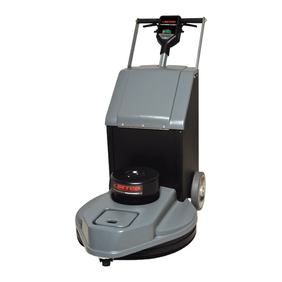
E85263-00 CREWMAN Dust Control ™ 20” Battery Burnisher Operator and Parts Manual 1001 Brown Avenue • Toledo, Ohio 43607-0127 Customer Service: 888-GO-BETCO • Fax: 800-445-5056 • Technical Service: 877-856-5954 • www.betco.com... -
Page 2: Table Of Contents
TABLE OF CONTENTS Technical Description ..........3 General Safety ............4 Loading, Unloading and Transporting .....5 Battery Charger Operation ........6 Battery Charger Settings .........7 Setup, Operation & Pad Pressure Adjustment ..8 Battery Discharge Indicator ........9 Pad Installation Instructions .........10 Assembly ..............11 Parts Diagrams ..........12 - 21 Maintenance ............22 Troubleshooting ............23 Warranty ...............24... -
Page 3: Technical Description
TECHNICAL DESCRIPTION Measurement Unit Crewman ™ Dust Control Battery Burnisher Burnish path in (mm) 20 (508) Pad size in (mm) 20 (508) Motor Motor speed 2000 Pad driver Flexible Pad Pressure Adjustable Volts Batteries V / AH (3) Maintenance free,12-volt, 110 AH, AGM Run time Up to 2.5 hour... -
Page 4: General Safety
Do not use machine as a “ladder”. Do not use machine as a “forklift” to push stuff around. Do not ride or let anyone ride on the machine. • Your machine warranty may be voided if parts other than Betco parts are used. -
Page 5: Loading, Unloading And Transporting
LOADING, UNLOADING AND TRANSPORTING DANGER: The machine is very heavy, so be very careful when loading, transporting, and unloading the machine. Use at least two people to load or unload the machine. LOADING PROCEDURE USING A RAMP • It is not recommended that the battery burnisher be loaded using a ramp with an incline of more than 7 degrees. The ma- chine is not self-propelled and therefore it is not able to assist itself up a ramp. -
Page 6: Battery Charger Operation
BATTERY CHARGER OPERATION CHARGER OPERATION • Plug the cord from the charger into a 110 volt outlet. • Batteries should now start charging. • A test is run on the battery voltage to decide if the charging process should be started or not. If the battery is not con- nected to the battery charger, the display will show the word “bat”. -
Page 7: Battery Charger Settings
BATTERY CHARGER SETTINGS DIP SWITCH INFORMATION The battery charger that was provided with the equipment is a programmable battery charger that can be optimized to the specific battery pack supplied with the machine. To access the programming DIP Switches your must remove the hard plastic label on the front of the charger. Be certain that the battery charger is unplugged from supply AC voltage and be certain that the battery charger is disconnected from the battery pack. -
Page 8: Setup, Operation & Pad Pressure Adjustment
INITIAL SETUP AND OPERATION 1. Remove the hardware from the Manual bag. 2. Raise the handle to the operating position and fasten with the two 1/2” x 5/16” bolts (A). 3. Tighten the other two bolts securely (A). 4. Hook the lanyard on the 1” bolt on left side of the ma- chine and fasten it with the Ny-Lok nut supplied. -
Page 9: Battery Discharge Indicator
BATTERY DISCHARGE INDICATOR CONNECTOR PIN CONFIGURATION (A) 1. Hour meter input – 2. Key + 3. Relay + 4. Relay – 5. Battery – 6. Not used 7. Not used 8. Battery + A. Shutoff voltage rotary dip switch. Factory set to 4 (32.76 volts). This is the voltage at which the batteries are 80% discharged. -
Page 10: Pad Installation Instructions
PAD INSTALLATION INSTRUCTIONS 1. Use only 19” or 20” diameter pads. Light hair pads work the best. 2. Turn the key switch off. 3. Tip the machine all the way back. 4. Remove the center lock (A). 5. Center the new pad on the pad holder, feel around the edges to ensure that the pad is centered. -
Page 11: Assembly
ASSEMBLY Handle Assembly Key Switch Box Assembly Battery Box Assembly Frame Assembly... -
Page 12: Parts Diagrams
HANDLE ASSEMBLY PARTS DIAGRAM E81099 E83691 E81180 E81105 E82751 E85032 E82749 E81139 E83130 E83270 E83426 E83427 E83731 E83129 E83522 E83127 E81275 E81058 E81095 EP50090 E81588 E81175 E81278 E81057... - Page 13 HANDLE ASSEMBLY PARTS LISTING PART Description QTY. NUMBER E81057 DCBB Handle Tube Weldment E81058 Handle Tube, 0.880" OD x 0.047" Wall x 14.375" E81095 Nut, 1/2"-13, Acorn, Zinc E81099 Screw, 1/4"-20 x 1.000", Pan Head E81105 Plate, Switch E81139 Wire, 16 AWG, Black, 4.00" L, 1 Female QD E81175 Bracket, Handle Leg DCBB E81180...
- Page 14 KEY SWITCH BOX ASSEMBLY PARTS DIAGRAM E89382 E12629 E12630 E81843 E81099 E81178 E81067 E89779 E89781 E81528 E81589 E81761 E81820 E81597 E81596 E81760 E81822 E81819...
- Page 15 KEY SWITCH BOX PARTS LISTING PART DESCRIPTION QTY. NUMBER E12629 SWITCH, KEYED, SPE, WITH 2 KEYS E12630 BDI (BATTERY DISCHARGE INDICATOR AND HOUR METER) E81067 LOCK WASHER 5/16 E81099 SCREW 1/4-20 x 0.875 E81178 BRACKET, SWITCH BOX E81528 CONTRACTOR 36VDC, 72 AMP E81589 SHUNT, 50 AMP, 50mV E81596...
- Page 16 BATTERY BOX ASSEMBLY PARTS DIAGRAM E88893 E10878 E83523 E12564 E86157 E12565 E88030 E81824 E81063 E81823 E81821 E81072 E81097 E12628 E81586 E81074 E81599 E83720 E88909 E81604 E81590 E81584 E81074 E81146 E81713 E81602 E81125 E88894 E81400 E10734 E88887 E83143...
- Page 17 BATTERY BOX PARTS LISTING PART Description QTY. NUMBER E10734 Screw, 1/4"-20 x 0.625 Hex Head, Grade 5, Zinc E10878 Anderson Plug, Gray E12564 Cable, 4 AWG, Red, 27.50" L, Lug 0.250" & Anderson Contact E12565 Cable, 4 AWG, Black, 23.50" L, Lug 0.250" & Anderson Contact E12628 Charger, SPE, 36V, 15A, AGM E81063...
- Page 18 FRAME ASSEMBLY PARTS DIAGRAM E81523 E81229 E81141 E81079 E81071 E81275 E81143 E81089 E83788 E81172 E81082 E81088 E12407 E81713 E81132 E12407 E81587 E88904 E88913 E81076 E81085 E81107 E81076 E81062 E83269 E88810 E83145 E88904 E12476 E81174 E81066 E81604 E81080 E81064 E81062 E81598 E81617 E81063 E81123...
- Page 19 FRAME BOX PARTS LISTING PART Description QTY. NUMBER E12407 Washer, 1/2" SAE, Zinc E12476 Screw, Shoulder 1/2" x 1/2" Socket Head E81061 Washer, Flat 3/4" ID X 1.25" OD X 0.075" Thick, Zinc E81062 Washer, 5/16" USS, Zinc E81063 Nut, 5/16"-18, Nylon Lock, Grade 5, Zinc E81064 Screw, 1/4"-20 x 0.750 Hex Head, Grade 5, Zinc E81066...
-
Page 20: Electrical Diagram
ELECTRICAL DIAGRAM 1 2 3 4 E88893 WIRE HARNESS E81820 E81819 E81821 E81822 E81824 E12564 E81823 E12565... - Page 21 ELECTRICAL DIAGRAM TRIGGER SWITCH KEY SWITCH INDICATOR LIGHT CLIP 10 AMP SHUNT 50 AMP METER MOTOR DCBB WIRING DIAGRAM REV.1; 02/2013...
-
Page 22: Maintenance
CREWMAN DUST CONTROL BATTERY ™ BURNISHER MAINTENANCE PERIODIC MAINTENANCE EVERY EVERY EVERY EVERY DAILY PLEASE REFER OWNERS MANUAL FOR MORE HOURS HOURS HOURS HOURS INFORMATION Empty the dust bag Wipe the machine with a damp cloth Charge batteries Make sure battery connections are tight and free from... -
Page 23: Troubleshooting
TROUBLESHOOTING PROBLEM CAUSE POSSIBLE SOLUTION Bad connection Check all connections No power, green power Bad connection to BDI Make sure connector is fully pushed into BDI lamp is off, no BDI Batteries dead Recharge or replace batteries as needed readout. Battery terminals disconnected ensure all terminal connections are clean and secure Power is on but won't run Circuit breakers tripped Turn off key switch and push each circuit breaker... -
Page 24: Warranty
Service Distributor. If the original part is returned within the warranty policy period from date of delivery for inspection by Betco and is found to be defective the owner will be credited for the cost of replacement parts plus shipping and handling.
Need help?
Do you have a question about the CREWMAN and is the answer not in the manual?
Questions and answers