Table of Contents
Advertisement
Quick Links
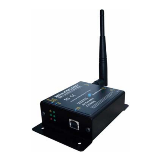
XBee-PRO PKG-U™ USB RF Modem
XBee-PRO USB RF Modem
RF Modem Operation
RF Modem Configuration
Appendices
Product Manual
For XBee-PRO RF Modem Part Numbers:
®
IEEE
802.15.4 Stand-alone USB RF Modems by MaxStream, Inc.
355 South 520 West, Suite 180
Lindon, UT 84042
Phone: (801) 765-9885
Fax: (801) 765-9895
rf-xperts@maxstream.net
www.MaxStream.net (live chat suport)
v1.x82
XBP24-PKC-...-U...
M100281
2006.04.24
Advertisement
Table of Contents

Subscribe to Our Youtube Channel
Related Manuals for MaxStream XBP24-PKC-...-U...


Summary of Contents for MaxStream XBP24-PKC-...-U...
- Page 1 Appendices Product Manual v1.x82 For XBee-PRO RF Modem Part Numbers: XBP24-PKC-...-U... ® IEEE 802.15.4 Stand-alone USB RF Modems by MaxStream, Inc. 355 South 520 West, Suite 180 Lindon, UT 84042 Phone: (801) 765-9885 Fax: (801) 765-9895 rf-xperts@maxstream.net M100281 www.MaxStream.net (live chat suport)
- Page 2 XBee‐PRO PKG‐U™ USB RF Modem – 802.15.4 ‐ Product Manual v1.x82 [2006.04.24] © 2006 MaxStream, Inc. All rights reserved No part of the contents of this manual may be transmitted or reproduced in any form or by any means without the written permission of MaxStream, Inc. XBee‐PRO PKG‐U™ is a trademark of MaxStream, Inc. Technical Support: Phone: (801) 765‐9885 Live Chat: www.maxstream.net E‐mail: rf‐xperts@maxstream.net © 2006 MaxStream, Inc., Confidential & Proprietary ‐ All Rights Reserved ii...
-
Page 3: Table Of Contents
2.4.1. NonBeacon 9 1-Year Warranty 49 2.4.2. NonBeacon (w/ Coordinator) 9 Ordering Information 49 2.4.3. Association 10 Contact MaxStream 50 2.5. Modes of Operation 13 2.5.1. Idle Mode 13 2.5.2. Transmit / Receive Modes 13 2.5.3. Sleep Mode 15 2.5.4. Command Mode 17 2.6. -
Page 4: Xbee-Pro Usb Rf Modem
1.1.1. Worldwide Acceptance FCC Approved (USA) Refer to Appendix A [p45] for FCC Requirements. Systems that include XBee-PRO RF Modems inherit MaxStream Certifications. Operates within the ISM (Industrial, Scientific & Medical) 2.4 GHz frequency band Manufactured under ISO 9001:2000 registered standards XBee-PRO RF Modems are optimized for use in US, Canada, Australia, Israel and Europe (contact MaxStream for complete list of approvals). -
Page 5: Specifications
Data Connection Operating Temperature 0 - 70º C (Commercial) Certifications (partial list) United States (FCC Part 15.247) OUR-XBEEPRO Industry Canada (IC) 4214A XBEEPRO Europe (CE) ETSI (Max. 10 mW transmit power output)* * When operating in Europe: XBee‐PRO RF Modems must be configured to operate at a maximum transmit power output level of 10 dBm. Set the PL parameter to “0” (10 dBm) in order to adhere to European regulations. 1.3. Mechanical Drawings Figure 1‐01. Mechanical drawings of the XBee‐PRO USB RF Modem © 2006 MaxStream, Inc., Confidential & Proprietary ‐ All Rights Reserved 5... -
Page 6: External Interface
Table 1‐02. USB signals and their implantations on the XBee‐PRO RF Modem Name Description Implementation VBUS Power Power the RF modem Transmitted & Received Data Transmit data to and from the RF modem Transmitted & Received Data Transmit data to and from the RF modem Ground Signal Ground © 2006 MaxStream, Inc., Confidential & Proprietary ‐ All Rights Reserved 6... -
Page 7: Rf Modem Operation
A USB client should not be plugged into another client. If another USB client (such as a USB video camera) is plugged into a MaxStream USB RF Modem (also a client), the devices will not commu- nicate. It would be incorrect to attach a USB modem to a host on one end and attach a USB modem to a USB client at the other end. -
Page 8: Transparent Operation
The API operation option facilitates many operations such as the examples cited below: -> Change destination addresses without having to enter command mode -> Receive success/failure status of each RF packet -> Identify the source address of each received packet To implement API operations, refer to API sections [p40]. © 2006 MaxStream, Inc., Confidential & Proprietary ‐ All Rights Reserved 8... -
Page 9: Ieee 802.15.4 Networks
Master/Slave relationships. This means that modems remain synchronized without use of master/server configurations and each modem in the network shares both roles of master and slave. MaxStream's peer-to-peer architecture features fast synchronization times and fast cold start times. This default configuration accommodates a wide range of RF data applications. -
Page 10: Association
Active Scan results. Otherwise, the ID (PAN ID) parameter setting will be updated to a PAN ID that was not detected. Not Set (bit 0 = 0) - The Coordinator retains its ID setting. No Active Scan is performed. © 2006 MaxStream, Inc., Confidential & Proprietary ‐ All Rights Reserved 10... - Page 11 BeaconRequest command as before. This process continues until all channels have been scanned, or until 5 PANs have been discovered. When the Active Scan is complete, the results include a list of PAN IDs and Channels that are being used by detected PANs. © 2006 MaxStream, Inc., Confidential & Proprietary ‐ All Rights Reserved 11...
- Page 12 4. End Device Changes once an End Device has associated Changing A1, ID or CH parameters will cause the End Device to disassociate and restart the Association procedure. If the End Device fails to associate, the AI command can give some indication of the failure. © 2006 MaxStream, Inc., Confidential & Proprietary ‐ All Rights Reserved 12...
-
Page 13: Modes Of Operation
Coordinator. Thus, if all devices in a network are End Devices, only Direct Trans- missions will occur. Indirect Transmissions are useful to ensure packet delivery to a sleeping device. The Coordinator currently is able to retain up to 2 indirect messages. © 2006 MaxStream, Inc., Confidential & Proprietary ‐ All Rights Reserved 13... - Page 14 If the transmission is not a broadcast message, the modem will expect to receive an acknowledge- ment from the destination device. If an acknowledgement is not received, the packet will be resent up to 3 more times. If the acknowledgement is not received after all transmissions, an ACK failure is recorded. © 2006 MaxStream, Inc., Confidential & Proprietary ‐ All Rights Reserved 14...
-
Page 15: Sleep Mode
DTR is asserted and is ready to transmit or receive when the CTS line is low. When waking the modem, the pin must be asserted at least two 'byte times' after CTS goes low. This assures that there is time for the data to enter the DI buffer. © 2006 MaxStream, Inc., Confidential & Proprietary ‐ All Rights Reserved 15... - Page 16 Coordinator will send a direct message to that remote instead of queuing it. The Coordinator is always awake so that any remote unit can transmit either a poll request or a data message at any time. © 2006 MaxStream, Inc., Confidential & Proprietary ‐ All Rights Reserved 16...
-
Page 17: Command Mode
If no valid AT Commands are received within the time specified by CT (Command Mode Timeout) Command, the RF modem automatically returns to Idle Mode. For an example that illustrates programming the RF modem using AT Commands, refer to the "RF Modem Configuration" chapter [p19]. © 2006 MaxStream, Inc., Confidential & Proprietary ‐ All Rights Reserved 17... -
Page 18: Addressing
Sample Network Configuration (All modems in the network): • DL (Destination Low Address) = 0x0000FFFF • DH (Destination High Address) = 0x00000000 (default value) NOTE: When programming the modem, parameters are entered in hexadecimal notation (without the “0x” prefix). Leading zeros may be omitted. © 2006 MaxStream, Inc., Confidential & Proprietary ‐ All Rights Reserved 18... -
Page 19: Rf Modem Configuration
USB connection to a PC. Install MaxStream's X-CTU Software to a PC by double-clicking the "setup_X-CTU.exe" file. (The file is located on the MaxStream CD and under the 'Software' section of the following web page: www.maxstream.net/helpdesk/download.php) Connect the RF modem to a PC. -
Page 20: Command Reference Tables
(802.15.4 - macMinBE). MAC Mode. Set/Read MAC Mode value. MAC Mode enables/disables the use of a Networking MaxStream header in the 802.15.4 RF packet. When Mode 0 is enabled (MM=0), 0 - 2 {Addressing} duplicate packet detection is enabled as well as certain AT commands. - Page 21 1 - Coordinator will perform Energy Scan to find a free channel, then operate on that channel. bit 2 - AllowAssociation - 0 - Coordinator will not allow any devices to associate to it. 1 - Coordinator will allow devices to associate to it. bits 3 - 7 are reserved © 2006 MaxStream, Inc., Confidential & Proprietary ‐ All Rights Reserved 21...
- Page 22 0 - 6 {Association} scan time on each channel is measured as Time = [(2 ^ED) * 15.36] ms. Note the total scan time is this time multiplied by the number of channels to be scanned. Refer to SD parameter. © 2006 MaxStream, Inc., Confidential & Proprietary ‐ All Rights Reserved 22...
- Page 23 2 - AD2/DIO2 Serial bit 3 - AD1/DIO1 0 - 0xFF 0xFF Interfacing bit 4 - AD0/DIO0 bit 5 - RTS bit 6 - SLEEP_RQ bit 7 - DIN/CONFIG “1” specifies pull-up enabled, “0” specifies no pull-up © 2006 MaxStream, Inc., Confidential & Proprietary ‐ All Rights Reserved 23...
- Page 24 The values returned represent the detected 0 - 7 energy level in units of -dBm. The actual scan time on each channel is measured as Time = [(2 ^ SD PARAM) * 15.36]ms. © 2006 MaxStream, Inc., Confidential & Proprietary ‐ All Rights Reserved 24...
- Page 25 Command Sequence Character. Set/Read the ASCII character value to be used AT Command 0x2B between Guard Times of the AT Command Mode Sequence (GT+CC+GT). The AT 0 - 0xFF Mode Options (‘+’ ASCII) Command Mode Sequence enters the RF modem into AT Command Mode. © 2006 MaxStream, Inc., Confidential & Proprietary ‐ All Rights Reserved 25...
-
Page 26: Command Descriptions
1 - Coordinator will perform Energy Scan to find a free channel, then operate on that channel. 0 - Coordinator will not allow any devices to associate to it. 2 - AllowAssociate 1 - Coordinator will allow devices to associate to it. 3 - 7 [reserved] The binary equivalent of the default value (0x06) is 00000110. ‘Bit 0’ is the last digit of the sequence. © 2006 MaxStream, Inc., Confidential & Proprietary ‐ All Rights Reserved 26... - Page 27 Parameter Range:0 - 2 based API operation. Parameter Configuration Disabled (UART operation) API enabled API enabled (with escaped characters) Refer to the “API Operation” section [p40] when API Default Parameter Value:0 operation is enabled (AP = 1 or 2). © 2006 MaxStream, Inc., Confidential & Proprietary ‐ All Rights Reserved 27...
- Page 28 The RF data rate is not affected by the BD param- 57600 eter. If the interface data rate is set higher than 115200 the RF data rate, a flow control configuration may need to be implemented. Default Parameter Value:3 Command description is continued on the next page. © 2006 MaxStream, Inc., Confidential & Proprietary ‐ All Rights Reserved 28...
- Page 29 BD register. For example, a rate of 19200 bps can be set by sending the following command line "ATBD4B00". NOTE: When using MaxStream’s X-CTU Software, non-standard interface data rates can only be set and read using the X-CTU ‘Ter- minal’...
- Page 30 <Serial Interfacing> The D6 command is used to AT Command: ATD6 set and read the behavior of the DIO6 line. This Parameter Range:0 - 1 line can be configured to enable RTS flow control. Parameter Configuration Disabled RTS Flow Control Default Parameter Value:0 © 2006 MaxStream, Inc., Confidential & Proprietary ‐ All Rights Reserved 30...
- Page 31 To transmit using a 16-bit address, set the DH parameter to zero and the DL parameter less than 0xFFFF. 0x000000000000FFFF (DL concatenated to DH) is the broadcast address for the PAN. Refer to the “Addressing” section [p18] for more information. © 2006 MaxStream, Inc., Confidential & Proprietary ‐ All Rights Reserved 31...
- Page 32 Time = [(2 ^ ED PARAM) * 15.36] ms. Note: Total scan time is this time multiplied by the number of channels to be scanned. Also refer to the SD (Scan Duration) table. Use the SC (Scan Channel) command to choose which channels to scan. © 2006 MaxStream, Inc., Confidential & Proprietary ‐ All Rights Reserved 32...
- Page 33 (802.15.4 + MaxStream header) mands. Modes 1 and 2 are strict 802.15.4 modes. 802.15.4 (no ACKs) When the MaxStream header is disabled, the ND 802.15.4 (with ACKs) (Node Discover) and DN (Destination Node) parameters are also disabled. Default Parameter Value:0 MY (16-bit Source Address) Command <Networking {Addressing}>...
- Page 34 PWM0 (Pulse Width Parameter Range: 0 - 1 Modulation Output 0). Parameter Configuration Note: The second character in the command is a Disabled zero (“0”), not the letter “O”. RSSI PWM0 enabled Default Parameter Value: 1 © 2006 MaxStream, Inc., Confidential & Proprietary ‐ All Rights Reserved 34...
- Page 35 The RE command does not write restored values to non-volatile (persistent) memory. Issue the WR (Write) command subsequent to issuing the RE command to save restored parameter values to non-volatile memory. © 2006 MaxStream, Inc., Confidential & Proprietary ‐ All Rights Reserved 35...
- Page 36 (0 percent PWM) until another RF packet is received. The PWM output will also be set low at power-up until the first RF packet is received. A parameter value of 0xFF permanently enables the PWM output and it will always reflect the value of the last received RF packet. © 2006 MaxStream, Inc., Confidential & Proprietary ‐ All Rights Reserved 36...
- Page 37 32 bits of the RF modem's unique IEEE Parameter Range: 0 - 0xFFFFFFFF [read-only] 64-bit address. Related Commands: SH (Serial Number High), The modem serial number is set at the factory MY (Source Address) and is read-only. © 2006 MaxStream, Inc., Confidential & Proprietary ‐ All Rights Reserved 37...
- Page 38 <Diagnostics> The VL command is used to read AT Command: ATVL detailed version information about the RF Parameter Range:0 - 0xFF modem. The information includes: [x 100 milliseconds] application build date; MAC, PHY and bootloader Default Parameter Value: 0x28 (40 decimal) versions; and build dates. © 2006 MaxStream, Inc., Confidential & Proprietary ‐ All Rights Reserved 38...
- Page 39 If changes are made without writing them to non-volatile memory, the modem reverts back to previously saved parameters the next time the modem is powered-on. NOTE: Once the WR command is sent to the modem, no additional characters should be sent until after the “OK/r” response is received. © 2006 MaxStream, Inc., Confidential & Proprietary ‐ All Rights Reserved 39...
-
Page 40: Api Operation
Escape characters. When sending or receiving a UART data frame, specific data values must be escaped (flagged) so they do not interfere with the UART or UART data frame operation. To escape an interfering data byte, insert 0x7D and follow it with the byte to be escaped XOR’d with 0x20. © 2006 MaxStream, Inc., Confidential & Proprietary ‐ All Rights Reserved 40... -
Page 41: Api Types
API Identifier Identifier-specific Data 0x8A cmdData Status (Byte 5) 0 = Hardware reset 1 = Watchdog timer reset 2 = Associated 3 = Disassociated 4 = Synchronization Lost (Beacon-enabled only) 5 = Coordinator realignment 6 = Coordinator reset © 2006 MaxStream, Inc., Confidential & Proprietary ‐ All Rights Reserved 41... - Page 42 If present, indicates the requested parameter correlate with a subsequent ACK (acknowledgement). ASCII characters that value to set the given register. If set to ‘0’, no response is requested. identify the AT Command. If no characters present, register is queried. © 2006 MaxStream, Inc., Confidential & Proprietary ‐ All Rights Reserved 42...
- Page 43 ACK (acknowledgement). 0x04 = Send packet with Broadcast Pan ID Up to 100 Bytes per packet Broadcast = 0xFFFF Setting Frame ID to ‘0' will disable response frame. All other bits must be set to 0. © 2006 MaxStream, Inc., Confidential & Proprietary ‐ All Rights Reserved 43...
- Page 44 Hexadecimal equivalent of (-dBm) value. bit 1 = Address broadcast Up to 100 Bytes per packet LSB (least significant) last (For example: If RX signal strength = -40 bit 2 = PAN broadcast dBm, “0x28” (40 decimal) is returned) bits 3-7 [reserved] © 2006 MaxStream, Inc., Confidential & Proprietary ‐ All Rights Reserved 44...
-
Page 45: Appendix A: Agency Certifications
IMPORTANT: The XBee-PRO USB RF Modem has been certified by the FCC for use with other products without any further certification (as per FCC section 2.1091). Modifications not expressly approved by MaxStream could void the user's authority to operate the equipment. IMPORTANT: OEMs must test final product to comply with unintentional radiators (FCC section 15.107 &... -
Page 46: Fcc-Approved Antennas (2.4 Ghz)
To ensure compliance, operations at closer than this distance is not recommended. The antenna used for this transmitter must not be co-located in conjunction with any other antenna or transmitter. The preceding statement must be included as a CAUTION statement in OEM product manuals in order to alert users of FCC RF Exposure compliance. © 2006 MaxStream, Inc., Confidential & Proprietary ‐ All Rights Reserved 46... -
Page 47: European Certification
EMC and safety. Files are located in the 'documentation' folder of the MaxStream CD. Important Note MaxStream does not list the entire set of standards that must be met for each country. MaxStream customers assume full responsibility for learning and meeting the required guidelines for each country in their distribution market. -
Page 48: Antenna Usage (Europe)
XBee-PRO (@ 10 dBm Transmit Power, PL parameter value must equal 0) The following antennas have been tested and approved for use with the embedded XBee-PRO RF Module: • Dipole (2.1 dBi, Articulated RPSMA, MaxStream part number A24-HABSM) • Chip Antenna (-1.5 dBi) • Attached Monopole Whip (1.5 dBi) The RF modem encasement was designed to accommodate the RPSMA antenna option. -
Page 49: Appendix B: Additional Information
1-year from the date of purchase. In the event of a product failure due to materials or workmanship, MaxStream will repair or replace the defective product. For warranty service, return the defective product to MaxStream, shipping prepaid, for prompt repair or replacement. -
Page 50: Contact Maxstream
XBee‐PRO PKG‐U™ USB RF Modem – 802.15.4 ‐ Product Manual v1.x82 [2006.04.24] Contact MaxStream Free and unlimited technical support is included with every MaxStream Radio Modem sold. For the best in wireless data solutions and support, please use the following resources: Documentation: www.maxstream.net/support/downloads.php Technical Support: Phone. (866) 765-9885 toll-free U.S.A. & Canada (801) 765-9885 Worldwide Live Chat.
Need help?
Do you have a question about the XBP24-PKC-...-U... and is the answer not in the manual?
Questions and answers