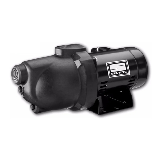
Summary of Contents for STA-RITE PNB-1L
- Page 1 OWNER’S MANUAL INSTALLATION AND OPERATING INSTRUCTIONS REPAIR PARTS LIST Corrosion Resistant Shallow Well Jet Pump MODELS 1/3 HP 1/2 HP 3/4 HP PNB-1L PNC-1L PND-1L PNCSS STA-RITE INDUSTRIES, INC., DELAVAN, WISCONSIN 53115 S151 (Rev. 4/17/95) PRINTED IN U.S.A.
-
Page 2: Table Of Contents
CORROSION RESISTANT Capacitor voltage may be hazardous. To dis- SHALLOW WELL JET PUMP charge motor capacitor, hold insulated handle screwdriver BY THE For domestic well installations with suction lifts of 25' or HANDLE and short capacitor terminals together. Do not touch less. -
Page 3: Before You Install Your Pump
BEFORE YOU INSTALL YOUR PUMP PUMP/PIPING INSTALLATION PUMP INSTALLATION PRE-INSTALLATION NOTICE: Use Teflon tape supplied with pump for making all 1. A pump cannot pump air. Make sure that suction pipe has threaded connections to pump itself. Do not use pipe joint com- no air leaks. - Page 4 WATER WATER WATER 157 0893 Figure 3-Tanks Pumping Cycle: 1. Tank nearly empty – air expands filling area above bladder (Fig. 2. Water enters tank – air is compressed above bladder as it fills with 179 0893 water (Fig. B). Figure 5- Pump on Pre-charged tank 3.
- Page 5 Priming plug Check valve Priming tee Priming plug Suction pipe Priming tee Steel drive pipe Standing water 20' (6 m) max. level (pump off) Suction pipe Foot valve Drawdown water always submerged level (pump on) Support pipe 10-20' (3-6 m) Drive coupling Screening protects foot valve...
- Page 6 ELECTRICAL Top view of Top view of Pressure Switch Pressure Switch Ground Ground 10-32 Grounding 10-32 Grounding Wire Wire screw (binding screw (binding head) under head) under motor canopy motor canopy White w/ Black Tracer Volt Volt White w/ Lines Lines Black Tracer Black...
-
Page 7: Pump Piping
OPERATION Your pump is designed for ease in servicing. Should repair or replacement of the motor or seal be needed, the pump and piping PRIMING THE PUMP do not need to be disconnected or disturbed. (FIG. 10) (If it is necessary to replace the motor, it is a good idea to replace Do not run pump with discharge shut off. - Page 8 REPLACING SHAFT SEAL 9. Slide rotating seal member (carbon face first) onto shaft until rub- ber drive ring hits shaft shoulder. REPLACING OLD SEAL NOTICE: BE SURE not to nick or scratch carbon face of seal 1. Follow steps 1 through 7 under Cleaning/Replacing Impeller when passing it over threaded shaft end or shaft shoulder.
-
Page 9: Helpful Hints
D. Clean out any surplus Permatex from insert cavity where new seal will be located. See Figure 16. Remove Surplus Permatex Properly Seated 039 0893 FIGURE 16 *”Permatex” is a registered trademark of Permatex Co., Inc. HELPFUL HINTS HOW TO HANDLE A GASEOUS WELL In some areas well water contains gases which must be allowed to escape before the water is used. -
Page 10: Troubleshooting Chart
TROUBLESHOOTING CHART SYMPTOM POSSIBLE CAUSE(S) CORRECTIVE ACTION Motor will not run Disconnect switch is off Be sure switch is on Fuse is blown or circuit has been tripped Replace fuse or reset circuit breaker Starting switch is defective DISCONNECT POWER; Replace starting switch Wires at motor are loose, Refer to instructions on wiring. - Page 11 REPAIR PARTS LIST 428 0893 Model and Horsepower 115V, 1/3 HP 115/230V, 1/2 HP 115/230V, 3/4 HP 115/230V, 1/2 HP Part Description Qty. PNB-1L PNC-1L PND-1L PNCSS Motor A100BHL A100CLL A100DLL A100CLL Water Slinger C69-2 C69-2 C69-2 C69-2 Seal Plate Assembly (Incl. #5)
-
Page 12: Warranty
LIMITED WARRANTY Sta-Rite warrants to the original consumer of the products listed below, that they will be free from defects in material and workmanship for the Warranty Period from the date of original installation or manufacture as noted. Product Warranty Period Water Systems Products –...


Need help?
Do you have a question about the PNB-1L and is the answer not in the manual?
Questions and answers