Table of Contents
Advertisement
Quick Links
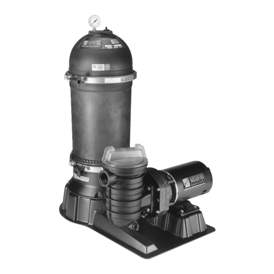
CARTRIDGE FILTER SYSTEM
FOR ABOVE-GROUND SWIMMING POOLS
Sta-Rite Pool/Spa Group
293 Wright Street, Delavan, WI 53115
North America: 800-752-0183, FAX 800-582-2217
International: 262-728-5551, FAX: 262-728-4461, TELEX: ITT 4970245
www.sta-ritepool.com
Union City, TN • Delavan, WI • Mississauga, Ont. • Murrieta, CA
© 2003, Sta-Rite Industries, Inc.
WATERFORD SYSTEMS
O
W
N
E
R '
INSTALLATION, OPERATION & PARTS
MODELS
PTM50JWAD-03
PTM50JWAD-04
PTM50JWAE-03
PTM50JWAE-04
PTM50JWAE-11
S
M
A
N
PTM70JWAD-03
PTM70JWAD-04
PTM70JWAE-03
PTM70JWAE-04
PTM70JWAE-11
Printed in U.S.A.
U
A
L
This manual should be furnished to
the end user of this system; its use
will reduce service calls and chance
of injury, and will add to the enjoy-
ment of the swimming pool.
S299 (Rev. 1/17/03)
Advertisement
Table of Contents

Subscribe to Our Youtube Channel
Related Manuals for STA-RITE PTM50JWAD-03


Summary of Contents for STA-RITE PTM50JWAD-03
- Page 1 293 Wright Street, Delavan, WI 53115 North America: 800-752-0183, FAX 800-582-2217 International: 262-728-5551, FAX: 262-728-4461, TELEX: ITT 4970245 www.sta-ritepool.com Union City, TN • Delavan, WI • Mississauga, Ont. • Murrieta, CA S299 (Rev. 1/17/03) © 2003, Sta-Rite Industries, Inc. Printed in U.S.A.
-
Page 2: Table Of Contents
“WATERFORD SYSTEMS” CARTRIDGE FILTER SYSTEM To avoid unneeded service calls, prevent possible injuries, and get the most out of your pump and filter, READ THIS MANUAL CAREFULLY! The Waterford Cartridge Filter System: • Is designed to circulate and filter water in above ground swimming pools. •... -
Page 3: Safety Instructions
• BE SURE all air is out of system before testing. cause minor personal injury or property damage if ig- • Tighten Sta-Rite trap lids to 30 ft. lbs. (4.1 kg-cm) nored. torque for testing. -
Page 4: General Information/Specifications
GENERAL INFORMATION NEVER operate this filter system at more than 50 PSI (345 kPa) pressure! NEVER test this filter system with compressed air. Maximum allowable water temperature is 110°F (43°C). Hazardous pressure. Can cause severe Plug system into electrically isolated, Ground Fault Circuit Interrupter injury or major protected circuit ONLY! property damage... -
Page 5: Installation
Discharge 1-1/2" NPT (to pool) Suction 33-1/2 1-1/2" NPT (851) (From pool) 11.3 (287) (180.4) (19) 12.6 (320) 16.8 (427) 25.4 (645.2) 20.33 (516) 807 0394 Figure 2 – Dimensions in Inches (mm) Figure 1 – Dimensions in Inches (mm) TABLE II DIMENSIONAL DATA IN ENGLISH (METRIC) Model Filter... - Page 6 SYSTEM SET-UP 1. Remove system from carton - Do not lift by piping. Place system base on level spot near pool skimmer with good drainage. 2. Install pressure gauge and air release valve (Key Nos. 1 and 2, Page 19) on filter lid assembly.
- Page 7 Piping: Use Teflon tape, Plasto-Joint Stik* or RTV #732** on threaded connections of plastic pipe and fittings (except unions). Do not use pipe compounds on plas- tic pipe or fittings; it may cause stress cracking of plastic components. Use 1-1/2" pipe to minimize flow restriction. If flex hose is used, use the type with smooth internal walls.
- Page 8 ELECTRICAL To avoid dangerous or fatal electrical shock, turn OFF power to motor before working on electrical connections. Plug the System into a Ground Fault Circuit Interrupter (GFCI) pro- tected receptacle on a 115 Volt, 60 Hertz grounded circuit only. GFCI tripping indicates an electrical problem.
-
Page 9: Operation
OPERATION To avoid explosion and possible severe or fatal injury, filter system pressure must not exceed 50 PSI (345 kPa) under any circumstances. NEVER test this filter system with compressed air. Never operate system with water temperature above 110°F (43°C). Do not block pump suction! To do so with body across pool skimmer or pool suction fitting may cause severe or fatal injury. -
Page 10: Maintenance
Water Maintenance: Keep water level at least two inches above bottom of skimmer opening when system is not in use. Failure to do so can allow air to enter system, causing pump to lose prime and filter to entrap air Maintain pH at 7.2 to 7.6 in pool. - Page 11 FILTER DISASSEMBLY Releasing either clamp with pressure on system will cause tank or tank head to blow off of base, causing severe injury or major property damage! NEVER adjust, tighten or loosen either “V” band clamp when tank is under pressure! Filter Disassembly: 1.
- Page 12 8. Install clamp(s) and knob assembly(s); tighten knob(s). To assist sealing, tap clamp(s) around tank with hammer while tightening knob(s). 9. Clean pump strainer basket. 10. Open system valves as needed. 11. Proceed to “Startup”, Page 9. STA-RITE APPROVED O-RING LUBRICANTS Parker Super-O-Lube* Semi-Permanent Lubrication Aqua-Lube by Allube** Semi-Permanent Lubrication...
- Page 13 Washing Filter Element (See Figures 9 and 10): 1. Use a garden hose with straight flow nozzle to wash down filter element (Figure 9). 2. Work from the top down; wash down all pleats. Wash between all pleats. 3. Turn element while spraying to wash down entire outside of element. 4.
- Page 14 PUMP SERVICE Removing Old Seal: 1. Disconnect power to pump motor. 2. Close suction and discharge valves. 3. Drain pump; disconnect unions to allow access to pump. Figure 12 4. Remove six bolts holding front plate to seal plate; remove front plate 5.
-
Page 15: Storage/Winterizing
STORAGE/WINTERIZING Store pool chemicals away from system in a well-ventilated area, to prevent damage from corrosive fumes. Do not add chemicals to pool directly in front of skimmer or pump suction. Adding undiluted chemicals may damage pump, valve or filter and will void the warranty. -
Page 16: Troubleshooting Guide
TROUBLESHOOTING GUIDE – PUMP Read and understand safety and operating instructions in this manual before doing any work on pump! A. PUMP DOES NOT OPERATE 1. Check GFCI (Ground Fault Circuit Interrupter) for proper operation ac- cording to GFCI manufacturer’s instructions. 2. - Page 17 TROUBLESHOOTING GUIDE A. Short Cycle: NOTICE: Time between cleanings will vary with each installation and be- tween different areas of the country. The following causes and remedies are for cycle times shorter than normal for your area. 1. Chlorine residual too low; maintain proper residual (consult pool pro- fessional for recommendation).
- Page 18 E. Filter Bypasses Dirt: To avoid severe injury or major property damage, exactly fol- low instructions under “Disassembly” and “Assembly” (Pages 11 and 12)! 1. Air bleed tube and/or tube filter not in position. Exactly follow instruc- tions in “Filter Disassembly/Assembly Procedure”, Pages 11 and 12, and reinstall correctly.
-
Page 19: Repair Parts List
EXPLODED VIEW 1782 0495 REPAIR PARTS LIST Part Description Qty. Systems Systems Systems Union Collar U11-182P1 U11-182P1 U11-182P1 Union Half & Nipple Assembly 25010-0202 25010-0202 25010-0202 O-ring, Union Coupling U9-226 U9-226 U9-226 Pump - 3/4 HP JWPA5D7L-2A2 JWPA5D7L-2A2 – Pump - 1 HP JWPA5E7L-2A2 JWPA5E7L-2A2 JWPA5E7L-2A1... - Page 20 EXPLODED VIEW 3, 3A 14, 14A NOTE: O-Rings, key numbers 4 and 7, are not interchangeable. REPAIR PARTS LIST Part Model Model Description Used PTM50 PTM70 Pressure Gauge 15060-0000T 15060-0000T Screen WC8-72D WC8-72D Air Release Valve Ass’y 25010-0200 25010-0200 Lid Ass’y (Includes Nos. 1, 1A, 2, and decals) 25010-9201 25010-9201 “O”...
- Page 21 REPAIR PARTS LIST – PUMP For -03, -04, and -11 Systems Trap Cover/“O” Ring Kit (5" trap) Kit includes C3-139P1 Trap Cover and U9-229 “O” Ring. Parts-Pak No. PP2075. 2596 0996 REPAIR PARTS LIST Model Number JWPA5E7L-2A2 JWPA5D7L-2A2 JWPA5E7L-2A1 Description Qty.
-
Page 23: Warranty
The foregoing warranties relate to the original consumer pur- chaser (“Purchaser”) only. Sta-Rite shall have the option to re- HRPB, DEPB, System 3, and PL – Tanks ..10 years pair or replace the defective product, at its sole discre- Internal filter components and valves .
Need help?
Do you have a question about the PTM50JWAD-03 and is the answer not in the manual?
Questions and answers