
Related Manuals for ekwb EK-Quantum Momentum Aorus Z490 Xtreme D-RGB


Summary of Contents for ekwb EK-Quantum Momentum Aorus Z490 Xtreme D-RGB
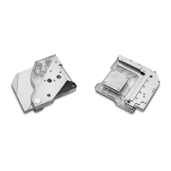
- Page 1 EK-Quantum Momentum Aorus Z490 Xtreme D-RGB MONOBLOCK USER GUIDE 1st Revision – December 15, 2020...
- Page 2 The following instructions are subject to change without notice. Please visit our website at www.ekwb.com for updates. Before installing this product, please read the important notice, disclosure, and warranty stipulation printed on the back of the box.
-
Page 3: Table Of Contents
TABLE OF CONTENT BOX CONTENTS MONOBLOCK DIMENSIONS INSTALLATION GUIDE SUPPORT AND SERVICE SOCIAL MEDIA - 3 -... -
Page 4: Box Contents
BOX CONTENTS CPU Water Block (1x) VRM Water Block (1x) Bridge Extenders (2x) Backplate (1x) Rubber Gasket (1x) Standoff (1x) Plasic Washer (4x) Thermal Pad F 120 x 16 x 1.0 mm (2x) Thermal Grease (1x) Spinner Head With Hex 4 and Hex 5 CPU Screw (4x) Spring (4x) Adapters (1x) -
Page 5: Monoblock Dimensions
MONOBLOCK DIMENSIONS 39 mm 154 mm - 5 -... -
Page 6: Installation Guide
INSTALLATION GUIDE STEP 1 Install your CPU first to prevent damaging the socket during monoblock installation. STEP 2 Once you remove eight screws as illustrated in the image (three M2x5 on the left and five M2x9 on the right), you can proceed to remove two front covers from the motherboard. - Page 7 STEP 3 Remove all thirteen screws that are holding the motherboard backplate and remove the backplate itself. Watch for the thermal pads – they might fall off in the process. Keep all these screws someplace safe since you will need them later. STEP 3 STEP 4 I/O Cover...
- Page 8 STEP 5 To remove the VRM heatsink from the motherboard, you must first remove the three standoffs and three screws. Save them all for later. Heatsink STEP 5 STEP 6 The rubber gasket is an essential part of the mounting mechanism and must be used.
- Page 9 STEP 7 Turn your motherboard face-down and position the rubber gasket and backplate directly in line with the mounting holes. The ribbed Metal Backplate side of the backplate should be facing up! Rubber gasket Motherboard STEP 7 STEP 8 Loosely install all four standoffs and plastic washers before Standoff - M4 x 21mm proceeding to tighten them completely.
- Page 10 STEP 9 Remove the six standoffs (2 shorter and 4 longer ones) from the stock VRM heatsink and install them to the VRM block. STEP 9 - 10 -...
- Page 11 STEP 10 Your monoblock comes with thermal pads that need to be trimmed Thermal Pad F 1.0 mm - (120 x 16 mm) to fit the voltage regulation area (MOSFET) on the motherboard’s circuit board. 1 mm Place larger strips of thermal pads over the marked area and make Thermal Pad F 1.0 mm sure all marked chips are covered, as shown in the picture.
- Page 12 STEP 11 Place the VRM block on the motherboard. Turn the motherboard face-down while holding the VRM block and install the three standoffs and three screws you saved in Step 4. STEP 11 STEP 12 Place the two bridge extenders (fittings) on the VRM block, and double-check that O-rings are in place.
- Page 13 STEP 13 Reassemble all of the motherboard covers. STEP 13a I/O shield, I/O cover, and I/O cover’s RGB cable with three standoffs and three screws: STEP 13a - 13 -...
- Page 14 STEP 13b Motherboard backplate with thirteen screws: STEP 13b STEP 13c Both front horizontal covers with eight screws: STEP 13c - 14 -...
- Page 15 STEP 14 Apply the enclosed EK-TIM Ectotherm thermal grease (thermal compound) on the CPU heat spreader – IHS – as shown in the image. The thermal compound layer must be thin and even in thickness over the entire surface of the IHS. The excessive or uneven application of thermal grease may lead to poor performance! STEP 14 STEP 15...
- Page 16 STEP 16 Insert all four springs inside the marked holes on the CPU water block. Spring STEP 16 STEP 17 Loosely insert all four CPU screws before proceeding to tighten CPU Screw them two revolutions at once in a cross pattern. When tightening the screws, do not use excessive force! STEP 17 - 16 -...
- Page 17 STEP 18 Plug the 4-pin D-RGB connector from your CPU water block in a D-RGB header on your motherboard or controller. The LEDs will work only if the pin layout on the header is as follows: +5V, Data, Empty, Ground. Incorrect installation or installation to the wrong header can result in damage to the LED Strip or the header itself! D-RGB Header...
-
Page 18: Support And Service
SUPPORT AND SERVICE In case you need assistance, please contact: https://www.ekwb.com/customer-support/ EKWB d.o.o. Pod lipami 18 1218 Komenda Slovenia - EU SOCIAL MEDIA EKWaterBlocks @EKWaterBlocks ekwaterblocks EKWBofficial ekwaterblocks...
Need help?
Do you have a question about the EK-Quantum Momentum Aorus Z490 Xtreme D-RGB and is the answer not in the manual?
Questions and answers