Advertisement
Quick Links
Advertisement

Subscribe to Our Youtube Channel
Related Manuals for Car Solutions QHI-XC90 U


Summary of Contents for Car Solutions QHI-XC90 U
- Page 1 Installation Manual Multimedia Interface for Volvo XC90 car-solutions.com support@car-solutions.com...
- Page 2 •Specification Car compatibility: Volvo XC90, S90 2017 Components : Interface* 1ea, Sub board*1ea Multimedia interface Input/output spec Input : Analog RGB*1(Navigation), HDMI*1, A/V*2, CVBS(Rear camera)*1, Output : To LCD*1 Power spec Input power : 8VDC ~ 18VDC consumption : 5WATT Switch input mode ...
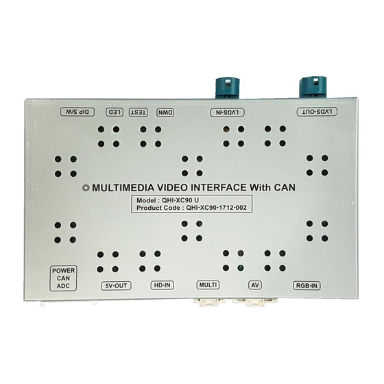
- Page 3 •Product Exterior •Components Power * 1ea LCD * 2ea RGB * 1ea MULTI * 1ea AV * 1ea (HLCDCA0017) (HRGBCA0026) (HARETC0240) (HAVCAB0056) REAR * 1ea BUTTON * 1ea IR * 1ea Remote * 1ea LCD Extension * 1ea (HARETC0002) (HARETC0001) (HIRCAB0002) (REMOTE0001) car-solutions.com...
- Page 4 * ON: DOWN / OFF: UP Please make sure to disconnect the power cable of interface and reconnect to apply dip switch setting whenever changing DIP switch. FUNCTION Dip S/W SELECT OFF : RGB Mode ON : RGB Mode Skip OFF : HDMI Mode HDMI ON : HDMI Mode Skip...
- Page 5 FUNCTION POWER & PIP MENU Activating OSD menu Making a selection, changing image display ▲ Moving upward ▼ Moving downward Moving leftward ◀ (If you press this button 2 seconds long, you can access the factory mode) Moving rightward ▶ (If you press this button 2 seconds long, you can reset all the data about user environment) car-solutions.com...
- Page 6 Menu of FACTORY IMAGE IMAGE H-POSITION PARK V-POSITION H-POSITION/V-POSITION Setting UTIL1 UTIL2 INFO MENU to Return SEL to Select/Save Menu of FACTORY IMAGE PAS TYPE PARK PAS SETUP UTIL1 REAR TYPE UTIL2 REAR SPLIT INFO MENU to Return SEL to Select/Save PARKING PAS TYPE: Select parking line type.
-
Page 7: Audio Out
Menu of FACTORY UTIL1 IMAGE NAVI MODEL NAVI MODEL: PARK AVOUT SELECT UTIL1 FCAM TIME Android, Car-play, Navigation Model Setting UTIL2 FACTORY RESET INFO AUDIO OUT: Select audio channel transmitted through AUX MENU to Return SEL to Select/Save (Default/AV1/AV2) FCAM TIME: Front Camera Display Setting FACTORY RESET: Factory mode reset (YES/NO) - Page 8 •OEM button ※ Press Home button to switch the mode * Press the button twice : Mode switch(RGB→HDMI1→A/V1→A/V2→F-CAM→OEM) * Short press : Back to OEM car-solutions.com support@car-solutions.com...
- Page 9 •Installation diagram RGB Pin #7 is UART-TX for UART Touch CAN1-H CAN1-L CAM2-H CAN2-L NAVI BOX BUTTON1 BUTTON2 HDMI Device A/V CABLE MULTI CABLE car-solutions.com support@car-solutions.com...
- Page 10 •CAN connection(GEAR, PAS) ※ Find OBD cable under the driver’s seat CAN Low : this cable is connected to CAN1-L(#4 pin) of the supplied power cable CAN High : this cable is connected to CAN1-H(#3pin) of the supplied power cable ※...
- Page 11 •CAN connection(GEAR, PAS) ※ CAN wires are not located at OBD parts. car-solutions.com support@car-solutions.com...
- Page 12 •LCD cable connection Find OEM blue Remove the OEM Connect the cable on the back blue cable supplied LCD cable side of the monitor to the same place. OEM cable Monitor 1. Connect Blue OEM cable to LCD extension connector and the supplied LCD cable is connected between LCD extension connector and LVDS-IN of the interface car-solutions.com...
- Page 13 1. Ignition key should be taken off before starting installation, interface power connection must be the last step in installation. 2. Power cable should be separated when connecting interface. 3. Should be no any electronic devices or magnetic pole around installation place.
- Page 14 Q. I cannot change mode A. Check connection of Ground cable and IR Cable. Check LED lamp is on, if not check connection of POWER cable. Q. All I got on the screen is black. A. Check second LED lamp of the interface is on, if not, check A/V sources connected are working well.
Need help?
Do you have a question about the QHI-XC90 U and is the answer not in the manual?
Questions and answers