Table of Contents
Advertisement
Quick Links
Video Interface for BMW E65
Specification & Installation
Specification & Installation
Compatible with BMW 7 Series(E65/66)
www.car-solutions.com
Model : QVL
Model :
QVL- - E65
E65- - V2
V2 / Product code :
Last updated: 2011.08.18
Last updated: 2011.08.18
/ Product code : BM
BM- - 0901
support@car-solutions.com
0901- - 652
652
Advertisement
Table of Contents

Related Manuals for Car Solutions QVL-E65-V2


Summary of Contents for Car Solutions QVL-E65-V2
- Page 1 Last updated: 2011.08.18 Last updated: 2011.08.18 Model : Model : QVL QVL- - E65 E65- - V2 V2 / Product code : / Product code : BM BM- - 0901 0901- - 652 Video Interface for BMW E65 Specification & Installation Specification &...
-
Page 2: Table Of Contents
Contents 1. Before installation 1.1 Main specification 1.2 Features 1.3 System diagram 1.4 Components 1.5 Exterior 1.6 POWER cable 2. Setup 2.1 DIP switch 2.2 Keypad usage 2.3 Remote control usage 2.4 Factory mode 2.5 OSD (on screen display) 2.6 Parking guide line 2.7 BMW Handle button NAVI setting 2.8 FMTX Frequency Setting 3. -
Page 3: Main Specification
1.1 Main specification 1. Input Spec. (MULTI VIDEO INTERFACE) -. 1 x Analog R,G,B (Sync on Green) -. 1 x CVBS(REAR CAMERA) Input. (Rear camera source) - 3 x A/V (NTST & PAL) Input. -. 1 x LCD Input (Car system Input) 2. -
Page 4: Features
1.2 Features - FMTX Module is added in the product. (No need additional FMTX Module for Audio) - Offering OSD Key Pad (The remote control is not offered anymore) - Possible to move the displayed position of Navi (Only on RGB mode) - Changed OSD MENU www.car-solutions.com... -
Page 5: System Diagram
1.3 System diagram Switch for source toggle OSD Keypad OEM NAVI Button (Can Interface) NAVIGATION Input (Analog RGB) DISPLAY Car Installation A/V 1 OEM LCD VIDEO MUX A/V 2 VIDEO CIRCUIT A/V 3 CVBS IN (Rear camera) Car Screen Input POWER A/V OUT (CAR MAIN BOARD) -
Page 6: Components
1.4 Components IR cable (8P) * 1ea CAN cable * 1ea Remote control * 1ea FPC cable * 1ea FFC cable (50P) * 1ea Ground cable * 1ea Keypad * 1ea MODE cable * 1ea AV cable * 1ea POWER cable (6P) * 1ea RGB cable * 1ea www.car-solutions.com... -
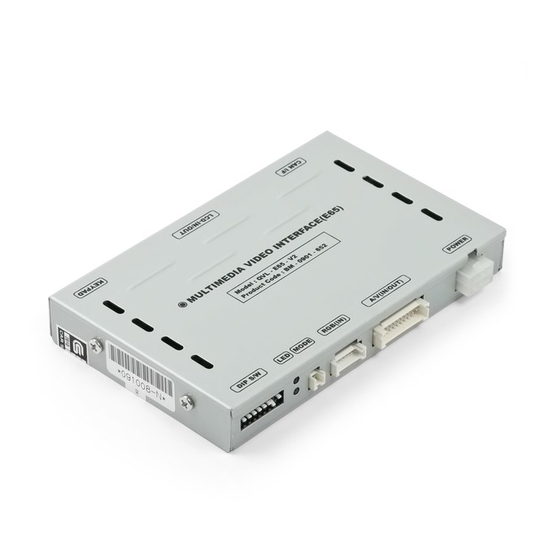
Page 7: Exterior
1.5 Exterior Dimension ⑦ ⑧ ⑨ Horizontal length 149mm Vertical length 91mm Height 19mm ① DIP switch ② LED ③ MODE ④ RBG IN ⑤ A/V(IN/OUT) ⑥ POWER ⑦ KEYPAD ⑧ LCD IN/OUT ⑨ CAN I/F ① ② ③ ④ ⑤... -
Page 8: Power Cable
1.6 POWER cable FILTER & FUSE BOX 파란색 FMTX 주황색 I - DRV 검정색 Gray 990mm Blue Orange 빨강색 회색 LAMP - RV Black 990mm www.car-solutions.com... -
Page 9: Dip Switch
2.1 DIP switch ※ ON : DOWN / OFF : UP #PIN FUNCTION DIP S/W Selection ON : Skipping RGB Mode RGB INPUT MUTE OFF : RGB Display ON : Skipping A/V 1 A/V 1 MUTE OFF : A/V1 Display ON : Skipping A/V 2 A/V 2 MUTE OFF : A/V2 Display... - Page 10 2.1 DIP switch #PIN Type of monitor E65 8.8” E65 6.5” [E65 8.8 Inch] ※DIP S/W Use Example [BMW E65-6.5 Inch] -. Use Input Mode : A/V3(DVD), Navigation (RGB) -. Rear Camera : When to be installed on CVBS 4 ▷...
-
Page 11: Keypad Usage
2.2 Keypad usage Select one between the remote controller and the keypad FACTORY MODE (Interface setting) : Press these buttons on OSD keypad in the following sequence; UP→DOWN→UP →MENU Function Function MENU/EXIT Activating OSD menu and Getting back to the previous state after setting mode SEL/INPUT Making a selection and hanging modes Moving leftward or upward (If you press this button 2 seconds long, you can get access... -
Page 12: Remote Control Usage
2.3 Remote control usage Function Function POWER & PIP Unavailable MENU Activating OSD menu Making a selection, changing image display Moving upward ▲ (If you press this button 2 seconds long, “Hot key” function will activate/ deactivate.) ▼ Moving downward Moving leftward ◀... -
Page 13: Factory Mode
2.4 FACTORY mode FACTORY mode : Operated with pressing UP->DOWN->UP->MENU keys on the keypad in sequent or Press ◀ button 2 seconds long on the remote control. I-DRV POSITION –To control DVD, Navi by I-DRV (Optional) – H-POSITION : moving in horizontal direction Refer to the “BMW Handle button NAVI setting”... -
Page 14: Osd (On Screen Display)
2.5 OSD (on screen display) COLOR -BRIGHTNESS -CONTRAST -RED -GREEN -BLUE -COLOR BOX : Selecting one among 3 color options -SATURATION -SHARPNESS Analog RGB Mode Video mode OPTION -OSD H_POS : Move of OSD window to Left, Right -OSD V_POS : Move of OSD window to Up, Down - OSD TRANS : OSD window transparency setting... -
Page 15: Parking Guide Line
2.6 Parking guide line Factory Default : DISPLAY - DISABLE ① When the car is in reverse, if ② If you need to move the line ③ On step no.2, once press “SEL” press ‘UP’ key for 2 sec, the position, press ‘SEL’... -
Page 16: Bmw Handle Button Navi Setting
2.7 BMW Handle Button NAVI setting Oversea After implementing FACTORY MODE (Interface setting), select I-DRV and press the Sel button of Keypad, and then Navi Setting window is displayed as shown right. After selecting the one among RGB, AV1~3, press the Sel button of keypad. (It is fine to select any channel, because the selecting of RGB, AV1~3 is useless. -
Page 17: Fmtx Frequency Setting
2.8 FMTX Frequency Setting Factory Default : FMTX USE – ON, FREQENCY – 87.5MHz Get the Factory Mode Operated with pressing UP->DOWN- >UP->MENU keys of the keypad in sequent. Set “FM-TX USE” to “ON” as shown left. (‘ON’ is Default). Control the frequency by “UP”, “Down”... -
Page 18: Cautions On Installation
3.1 Cautions on installation Ignition key should be taken off before starting installation, interface power connection must be the last step in installation. Power cable should be separated when connecting interface. Should be no any electronic devices or magnetic pole around installation place. ... -
Page 19: Can Installation
3.2 CAN Installation E65 CAN Wiring Diagram Orange: CAN HIGH Green: CAN LOW www.car-solutions.com... -
Page 20: Installation
3.3 Installation 2. Connect the FFC cable to the LCD-IN/OUT 1. Connect the FFC cable to FPC cable as connector of the board as shown above. shown above. 4. Connect the FPC cable to the connector of 3. Connect the LVDS cable of head unit to head unit as shown above. -
Page 21: Troubleshooting
4. Troubleshooting Q. I can not switch A/V sources A. Check IR or Ground cable connection. Check LED lamps in the interface, if it is not on, check power cable. Q. All I got on the screen is black. A. Check second LED lamp of the interface is on, if not, check A/V sources connected are working well. (Second lamp indicates AV sources connected works well.) Check interface connection has been done well.
Need help?
Do you have a question about the QVL-E65-V2 and is the answer not in the manual?
Questions and answers