Nice RUN1800 Installation Instructions Manual
Sliding
Hide thumbs
Also See for RUN1800:
- Instructions and warnings for the fitter (184 pages) ,
- Instructions and warnings for installation and use (56 pages) ,
- Instructions and warnings for the fitter (32 pages)
Table of Contents
Advertisement
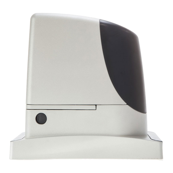
Run
Sliding Gate Opener
RUN 2500I Inverter
Instructions et recommandations pour l'installateur
Aanwijzingen en aanbevelingen voor de installateur
RUN1800
RUN1800P
RUN2500
RUN2500P
Instructions and warnings for the fitter
Istruzioni ed avvertenze per l'installatore
Anweisungen und Hinweise für den Installateur
Instrucciones y advertencias para el instalador
Instrukcje i uwagi dla instalatora
Advertisement
Table of Contents


Need help?
Do you have a question about the RUN1800 and is the answer not in the manual?
Questions and answers