
Related Manuals for Nice DC Blue ASTUTE


Summary of Contents for Nice DC Blue ASTUTE
- Page 1 03502-001-NICE DCBAST2024_ HW01_00_ FW28_ 00_ INSTALLER_ 03_ 00 Installer Instructions. Domestic, Sectional Overhead and Trackless Tip-up Door Operator...
-
Page 2: Hardware Installation
Introduction Page 3 Be Safe! Instructions, Warnings And Obligations. Page 4 Technical Specifications. Page 5 Component Identification. Hardware Installation. Page 6 Sectional Overhead Garage Door. Page 9 Trackless Tip-Up Garage Door. (Standard) Page 10 Trackless Tip-Up Garage Door. (Low Headroom) Page 12 Attach The Motor-head To The Drawbar. - Page 3 All Nice Group SA (Pty) Ltd garage door operators are supplied with a sealed 15A safety plug on lead for use in an electrical code of practice approved plug point. Do not extend, modify or replace the plug lead unless duly qualified as an electrician. Before installing the unit, ensure the mains supply is switched off.
-
Page 4: Technical Specifications
Is proficient in testing the unit’s safety obstruction sensing system. Is aware of what to check for with regards to wear and tear that may need to be attended to from time to time by the service provider. Is aware that a fatigued battery may not be disposed of in the general refuse and must be handed in at a battery merchant for safe disposal. Before removing the battery from the system the household mains must be disconnected. -
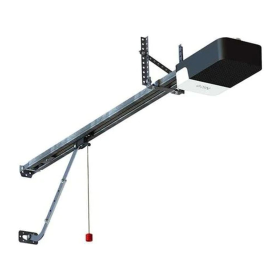
Page 5: Components Identification
Components Identification. 11 & 3 7 & 8 17 & 18 17 & 18 11 & 3 17 & 18 17 & 18 17 & 18 17 & 18 15 & 16 Image Number and Description Qty Image Number and Description Wall/Front mount bracket Drawbar spring shock absorber Pivot pin 8mm x 90mm... - Page 6 Hardware Installation - Sectional Overhead Garage Door. INSTALL THE MANUAL OVERRIDE CLUTCH ASSEMBLY ONTO THE SLEDGE/TRAVELLER (See page 5 for component identification) Using the 4 x Round head machine screws M6 x 20mm fasten the emergency release assembly onto the sledge/traveller as shown here. Ensure the 4 machine screws are securely fastened.
- Page 7 Hardware Installation - Sectional Overhead Garage Door. INSTALLTHE DRAWBAR AND HANGING STRAPS (See page 5 for component identification) Drawbar Hanging straps Install the drawbar in position as shown here. Ensure it is level using a spirit level. Below are a few examples of how to install the hanging straps. Install one section of hanging strap as a cross brace.
- Page 8 Hardware Installation - Sectional Overhead Garage Door. INSTALLING THE LINK ARM (See page 5 for component identification) Close the door fully. Install the curved link arm extension in the door mount bracket using one of the cotter pins and 25mm long pivot pins supplied.
- Page 9 Hardware Installation - Trackless Tip-Up Garage Door. (Standard) INSTALL THE WALL/FRONT MOUNT BRACKET (See page 5 for component identification) From the top edge of the door in the closed position, measure 275 – 300mm perpendicular to the top edge of the door. Install the wall/front mount bracket at this height where it is positioned above the centre of the door as shown in the diagram below.
- Page 10 Hardware Installation - Trackless Tip-Up Garage Door. (Standard) INSTALL THE LINK ARM AND HANGING STRAPS (See page 5 for component identification) Install the front end of the drawbar in the wall mount bracket using the 90mm pivot pin and one of the cotter pins. Raise the drawbar up and out of the way of the door.
- Page 11 Hardware Installation - Trackless Tip-Up Garage Door. (Low Headroom) INSTALL THE DRAWBAR (See page 5 for component identification) Install the front end of the drawbar in the wall mount bracket using the 90mm pivot pin and one of the cotter pins. install the hanging strap drawbar attachment bracket on the drawbar.
- Page 12 Hardware Installation - All versions. ATTACH THE MOTOR-HEAD TO THE DRAWBAR (See page 5 for component identification) Insert the splined motor drive shaft into the splined sprocket at the back-end of the drawbar. Swivel the motor-head around so that the motor mounting straps are able to fit over the drawbar and onto the mounting studs on the motor-head.
- Page 13 Electrical Installation - In Case The Battery Needs Replacing. NB! Disconnect the operator from the 230V supply by unplugging it, before removing the cover.. Remove the cover by removing the four cover screws. Take care to not drop the cover as you remove the last screw. Unplug the battery from the main control card.
- Page 14 Electrical Installation - Control Card Layout And Wiring. 8A Fast blow fuse +12V...
-
Page 15: Navigation Guide
Using The Dashboard And Programming Menu Quick Guide. Master erasing all remote button codes from the receiver memory (Pg 23) Clearing a single remote button code from the receiver memory (Pg 22) Program a transmitter button code into the (LT) courtesy light channel (Pg 20) Battery cell type selection (Pg 24) Program a transmitter button code into the (BT) button trigger channel (Pg 20) - Page 16 Limit Setup. (Standard) Open and closed limit position setup and door load profiling. NB! If all of the steps in this procedure are not completed correctly, then there will be no limit or From Standby status door profile settings in memory. An “8” will flash on the screen if attempting to run the door nor- mally with no limit or door profile settings in memory.
- Page 17 Limit Setup. (Extended Closing Ramp-down.) Open and closed limit position setup and door load profiling with extended closing ramp down for use on sectional overhead doors that have quick closure brackets. NB! If all of the steps in this procedure are not completed correctly, then there will be no From Standby status limit or door profile settings in memory.
- Page 18 Force - Safety Obstruction Sensing Setup. Setting the obstruction force sensing, safety level. From Standby status Factory default level = 3. Response Action Description Display Buzzer To enter the program menu. Press and hold Display and buzzer confirms. the “SET” button until buzzer beeps.
- Page 19 Safety Beams Setup. NB! When auto-close mode is activated, the safety beam mode automatically becomes active. With auto-close active, safety beam setup mode is no longer available in the programming menu. From Standby status When installing the safety beams, note that the 100 Ohm resistor must be installed as per page 14.
- Page 20 Receiver Setup. Adding A Transmitter Button. (Both Channels) Please note that if an ET BLU MIX © transmitter is being used and not all of the buttons have been From Standby status set to the same format, then the receiver will allocate two different user addresses for the various buttons.
- Page 21 Receiver Setup. Adding A Transmitter Button - Quick Method. (BT Channel Only) A quick method of learning a transmitter button code into the receiver memory without entering the programming menu. From Standby status NB!! No remote codes can be learnt into the (LT) courtesy light channel this way. Response Action Description...
- Page 22 Receiver Setup. Clearing A Single Transmitter Button From The Memory. Please note, to use this method, you need to know the user address that was allocated to the From Standby status transmitter when it was added to the receiver memory. No other transmitters will be cleared from the memory when using the method.
- Page 23 Receiver Setup. Erasing All Users From The Receiver Memory (Master Erase). Please note, to use this method, you need to know the user address that was allocated to the From Standby status transmitter when it was added to the receiver memory. No other transmitters will be cleared from the memory when using the method.
- Page 24 Cell Type - Battery Cell Type Selection. This function selects the level the battery low monitoring indication will begin sounding before the battery is fully depleted. There is an option to switch this warning off, where the unit will only give From Standby status a battery status indication when the battery is fully depleted.
- Page 25 Operating Features - Using The BT (Button Trigger). Open/Close Trigger. Response Action Door Light Display Buzzer Door closed. Press and release either the remote button trigger Door begins opening. or the hardwired trigger. Door reaches the Door stops and operator programmed open reverts to standby.
- Page 26 Operating Features - How the Safety Beams Work. Response Action Door Light Display Buzzer Door in open position. 3 Min. Press and release either the remote button trigger Door begins closing. or the hardwired trigger. 3 Min. Obstruct the safety Door stops and opens again.
- Page 27 Operating Features - How the Lock-out works. (Temporaily prevent triggering of the door) Response Action Door Light Display Buzzer To enable: Door in any position. Buzzer sounds for 5 Press and hold any LT seconds. Light channel button NB! If the BT channel button until buzzer starts is not press now, the lock- 5 Sec.
- Page 28 Status Indications and Diagnostics. Response Action. Reason Remedy (What you did) Door Light Display Buzzer Any normal Replace, Door physically trigger to damaged jammed. Motor relay start door encoder or relay. STOP or encoder damaged. running. free-up door. Remove obstruction. Or Door physically adjust safety While door is...
- Page 29 WARRANTY: All DC Blue Astute Garage Door Operators manufactured by Nice Group SA (Pty) Ltd carry a 24 month factory warranty from date of invoice. All goods are warranted to be free of faulty components and manufacturing defects. Faulty goods will be repaired or replaced at the sole discretion of Nice Group SA (Pty) Ltd free of charge. Within the warranty period.
Need help?
Do you have a question about the DC Blue ASTUTE and is the answer not in the manual?
Questions and answers