Table of Contents
Advertisement
Quick Links
Advertisement
Table of Contents

Subscribe to Our Youtube Channel
Related Manuals for Nice 3501


Summary of Contents for Nice 3501
- Page 1 Nice Swing Gate Operator Model 3501 Vehicular Swing Gate Operator 1050 Control Board CBOX with 1050 control board CHBOX35 ABOX35 Programming & controls, connections and safety information provided in the 1551 manual in CBOX Revision 4.0.0.0_1-2019 Part #10001450...
-
Page 3: Table Of Contents
30 - OPERATOR DIMENSIONS 15 - WIRING 30.1 - Control Box General Dimensions 15.1 - Incoming power wiring 30.2 - 3501 General Overview 15.2 - Chassis wiring 15.3 - Limit and motor wiring 31 - EXPLODED VIEWS 31.1 - Control box 16 - SETTING THE LIMIT SWITCHES 31.2 - Motor Chassis... -
Page 4: Overview
The “Learn” This manual covers the following Nice operator function helps gate installer confi gure Nice 1050 models: 3501 with 1050 (see 1551 manual for 1050 control board semi-automatically for optimum board programming and controls available). -
Page 5: General Safety Information
1.4 Product Specifi cations components operate together as a system. It is the responsibility of the system designer and/or Model 3501 installer to ensure any safety or operational issues Electrical Data have been addressed. Power Supply... - Page 6 Some operators are restricted in their usage application. All Nice USA operators are approved for use in all four UL325 Usage Classes. Appropriate Usage Classes are shown in the Specifi cations.
- Page 7 Locate the gate such that persons will not 2.10 When utilizing a Nice 1050 board, a come in contact with the vehicular gate during maximum of 10 entrapment protection the entire path of travel of the vehicular gate.
-
Page 8: Use Of Vehicle Detectors
4. Gate Construction and Safety 2.12 For a gate operator utilizing a contact sensor (Edge): Gate construction plays a very important role in ensuring the safety of any automated gate system. a. One or more contact sensors shall be The standard for gate construction is ASTM F2200. located where the risk of entrapment or Below are key areas to address safety in gate obstruction exists, such as at the leading... - Page 9 4.1.8 Gates shall be designed, constructed and 4.2.1.3 A gap, measured in the horizontal installed such that their movement shall not plane parallel to the roadway, between be initiated by gravity when an automatic a fixed stationary object nearest the operator is disconnected.
-
Page 10: Maintenance Of Gate Systems
4.3 Vehicular Horizontal Swing Gates 5. Maintenance of Gate Systems 4.3.1 The following provisions shall apply to To keep your automated gate system performing Class I, Class II, and Class III horizontal swing both safely and reliably it is important to ensure gates: that the components of that system are functioning properly. -
Page 11: Entrapment Protection
6. Entrapment Protection a. The gap between the bottom of a moving gate and the ground is greater than 4 in. The UL325 standard for gate operators requires (101.6 mm) and less than 16 in. (406 mm); or a minimum of two independent entrapment b. -
Page 12: Compatible External Sensors
Entrapment System (IES) (UL325 Type A) that Only the following external sensors have been monitors the force on the gate during travel. evaluated and tested with Nice gate systems and This system protects in both the open and are approved to be used for protection against... -
Page 13: Parts Identification
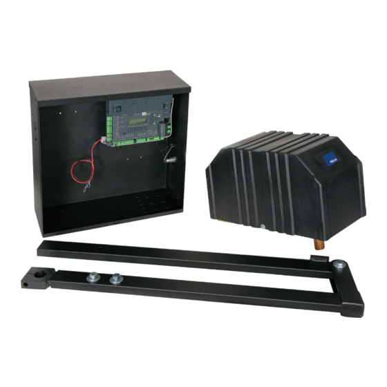
8 - PARTS IDENTIFICATION Arm Assembly #ABOX350 Chassis #CHBOX350 Control Box #CBOX1050 9 - POST INSTALLATION IMPORTANT - Never weld parts to the gate or posts when the operator circuit board is powered. Doing so may damage the board beyond repair. 9.1 - Post location guide Determine the angle that the gate will open to (A). -
Page 14: Post Height
9 - POST INSTALLATION (CONT.) OPTIMUM SETTING SHOWN IN GREEN Approximate Open Degrees Inches Inches Inches Inches seconds to open 31.2 46.3 40.6 47.1 42.1 13.5 25.5 46.3 46.8 47.1 43.7 42.4 53.5 37.4 50.6 39.3 58.4 44.3 50.3 9.2 - Post height The 3500 operator is designed for installation using a 4”x4”... -
Page 15: Chassis Mounting
10 - CHASSIS MOUNTING Set the chassis on the mounting plate as shown and secure using (4) 1/2” x 3/4” hex bolts and lock washers. Chassis should be mounted to plate so that the shaft for the arm connection is on the opposite side of mounting plate from the gate when in the closed position. -
Page 16: Gate Bracket Mounting
11 - CONTROL ARM ASSEMBLY (CONT.) Attach the secondary arm to the primary arm using a 1/2” x 2-1/4” hex bolt, brass washers and lock nut. The stop tab should be positioned away from the gate. Install the aluminum adjustable arm to the secondary arm using the 1/2”... -
Page 17: Control Box Mounting
13 - CONTROL BOX MOUNTING Mount the control box at least 6 feet from any moving part of the gate. There is 12 feet of cord provided for mounting flexibility. Use mounting hardware capable of supporting the weight of the control box with the battery installed. -
Page 18: Wiring
15 - WIRING 15.1 - Incoming power wiring Power input connections should be wired as follows: Solar panel Connect wires to the solar panel terminal block. The positive wire of the panel connects to the left terminal marked “+”. Note: If the panel is connected backwards a red LED will illuminate below the terminal. -
Page 19: Limit And Motor Wiring
3501 WIRING (LEFT HINGED GATE) 3501 WIRING (RIGHT HINGED GATE) Limit switch wiring Limit switch wiring Connect the 3501 cable to the 5-pin connector as shown below. Connect the 3501 cable to the 5-pin connector as shown below. Motor wiring Motor wiring... -
Page 20: Setting The Limit Switches
16 - SETTING THE LIMIT SWITCHES When first powered on, the board will scan for any BlueBuss photo eyes connected. If at least one eye is not detected, then one of the auxiliary inputs must be programmed to either pulse open or pulse close, with an External Entrapment sensor connected before learn mode is initiated. -
Page 21: Learning Mode
17 - LEARNING MODE Nice has taken great care to simplify the installation, operation and safety of this device and to ensure longevity and reliability of the unit over time. The learning procedure consists of the following steps shown below:... -
Page 22: Accessory Inputs And Outputs
18 - ACCESSORY INPUTS AND OUTPUTS 18.1 - Outputs GATE OPERATOR ACCESSORY INPUTS: Auxiliary Inputs 1 (16) and 2 (18): These digital inputs may be connected to the digital outputs of accessories and programmed to activate or control the gate operator in a number of different modes. Shorting the pins through a dry contact activates the programmed settings for these inputs. - Page 23 Receiver with the affected Nice remote control. The gate operator includes a two-pin connector designed to link two separate 1. Press and hold the button on the side of the Nice receiver until the led on gate operators together as a Master/Slave pair. The Master/Slave configuration the Nice receiver illuminates green and keep the button pressed.
-
Page 24: 120Vac Power Wiring
The following table should be used as a guide for capacity of operation of 1. Press and hold the button on the side of the Nice receiver until the led on operators only, additional options and accessories may reduce the daily usage. -
Page 25: Optional Inputs
21 - OPTIONAL INPUTS 21.1 - Fire dept. connection 21.3 - Guard station 32 FIRE 34 OPEN 33 GND 35 STOP 36 CLOSE Dry contact input for a fire department control switch. Normally Open (NO) 37 GND contact must be shorted to ground through a switch to open the gate. The FAIL SAFE connector which is shorted at the factory with a jumper (Normally With the Guard Station switches installed, the user can operate the gate by pushing the respective buttons for the command that is desired. -
Page 26: Radio Receiver Connection (Third Party)
21 - OPTIONAL INPUTS (CONT.) 22 - INSPECTION AND OPERATION Proper inspection of all equipment is required to ensure continuous functionality, 21.5 - Radio receiver connection (third party) safety and to ensure reliable operation in all weather conditions. Inspect electrical 38 12V assemblies and wiring installations for damage, general condition, and proper 39 OPEN... -
Page 27: General Layout And Safety Access
23 - GENERAL LAYOUT AND SAFETY ACCESS Entrapment Protection Inputs - Typical Installation Diagram Utilizing Loop Sensors and Photocells Safety Loop 4’ Min. from closed gate 4’ Min. from closed gate Loop (Shadow) Open Direction Eye Open Direction Eye Safety Loop Loop (Exit) Figure - LAYOUT FOR IN-GROUND LOOPS... -
Page 28: Accessories And Sensors
24 - ACCESSORIES AND SENSORS EXTERNAL ENTRAPMENT PROTECTION Non-contact and contact sensors must be installed individually or in combination with each other to provide external entrapment protection. Care should be exercised to reduce the risk of nuisance tripping, such as when a vehicle trips the sensor while the gate is still moving, and one or more non- contact sensors shall be located where the risk of entrapment or obstruction exists, such as the perimeter reachable by a moving gate or barrier. -
Page 29: Irb-Ret Wiring Diagram
25 - IRB-RET Wiring Diagram 2 FREQUENCY IRB-RET 1. Press “Functions” 2. Select #3 “Auxiliary IO” and Press “OK” 3. Select “In Aux 1” (or “In Aux 2”) and Press “OK”. 4. Select “Pulse Open” or “Pulse Close” and “Press OK” 5. -
Page 30: Wel-200 Wiring Diagram
27 - WEL-200 Wiring Diagram EMX WEL-200 Wireless Edge Receiver Dip Switch Settings determine which relay activates when the associated edge is tripped. See WEL-200 manual for instructions for programming receiver/transmitter pairs. To Terminal 20 – 24V To Terminal 21 – GND To Terminal 16 or 18 –... -
Page 31: Maintenance Schedule
28 - MAINTENANCE SCHEDULE Table 2 BASIC COMPLETE Alarm Activate the primary (inherent) reverse system by blocking the gate with a solid object. The gate should reverse momentarily then stop. Restart the gate and block again with a solid object. The gate should reverse momentarily, then stop, and go into hard shutdown with an alarm Backup System If operator is equipped with option DC backup system, check to be sure the system opens the... - Page 32 29 - TROUBLESHOOTING (CONT.) Table 4: 1050 Board Display Read Out and Troubleshooting DISPLAY REASON POSSIBLE SOLUTION Dynamic M1 Actuator connected to Motor Check for obstruction in gate path or degraded gate hardware. 1 has a brief current spike and tripped Type A sensor.
-
Page 38: Warranty
Nice Group USA Limited Warranty – 2 (TWO) YEARS Nice Group USA (“Manufacturer”) warrants this product shall be free from defects in materials and workmanship for a period of 2 years from the manufacture date. These warranties are in lieu of all other warranties expressed or implied and shall be considered void if the product is damaged due to, but not limited to, improper installation, improper use, terrorism or acts of God. -
Page 39: Installation Checklist
33 - INSTALLATION CHECKLIST Left box is for installer check off and the right box is for customer check off. 1. The gate has been checked to make sure it is level and moves freely in both directions. 2. Potential pinch areas have been guarded so as to be inaccessible OR have contact and/or non-contact obstruction sensing devices installed. -
Page 40: Appendix - French Translations
34 - Appendix - French Translations FRENCH TRANSLATIONS The following French translations provided below are found in the Safety Section located at the beginning of the manual. English French INSTRUCTIONS DE SÉCURITÉ IMPORTANTES IMPORTANT SAFETY INSTRUCTIONS AVERTISSEMENT – Pour réduire les risques de WARNING –... - Page 41 34 - Appendix - French Translations (Cont.) English French Install the gate operator only when: N’installez l’ouvre-barrière que si : The operator is appropriate for the construction l’ouvre-barrière est approprié pour la structure et of the gate and the usage Class of the gate, la classe d’utilisation de la barrière;...
- Page 42 34 - Appendix - French Translations (Cont.) English French Les commandes destinées à l’activation par Controls intended for user activation must be l’utilisateur doivent être situées à au moins 1,83 located at least 1.83 m (6 ft) away from any m (6 pi) des pièces mobiles de la barrière et à...
- Page 43 34 - Appendix - French Translations (Cont.) English French A hardwired contact sensor shall be located and Un capteur de contact doit être installé et câblé its wiring arranged so that the communication de sorte à éviter que la communication entre between the sensor and the gate operator is not le capteur et l’ouvrebarrière soit gênée par des subjected to mechanical damage.
- Page 44 Contact us Nice 6705 S. 209th St., Suite 101 Kent, WA 98032-2327 Ph. +1.253.867.3700 Fax +1.253.867.3702 www.hysecurity.com www.facebook.com/hsgateoperators...
Need help?
Do you have a question about the 3501 and is the answer not in the manual?
Questions and answers