
Subscribe to Our Youtube Channel
Related Manuals for APV Tined Weeder Pro VS 150 M1


Summary of Contents for APV Tined Weeder Pro VS 150 M1
- Page 1 Version: 1.0 EN Item no.: 00602-3-205 Operating manual for the Tined Weeder Pro VS 150 M1, VS 300 M1 Please read carefully before initial operation! TRANSLATION OF THE ORIGINAL OPERATING MANUAL...
-
Page 2: Table Of Contents
Contents EC Declaration of Conformity ..................... 4 Identification of the implement ................... 5 Service ..........................5 Warranty..........................6 Warranty activation ....................6 Safety information ....................... 6 Intended use ......................6 General safety-related instructions and accident prevention regulations ....7 Mounted implements ....................8 Hydraulic system ...................... - Page 3 Cropping tips for using the Tined Weeder Pro ..............26 Accessories ........................27 Spare parts ........................29 Index ........................... 29 Translation of the original operating manual Page 3...
-
Page 4: Ec Declaration Of Conformity
This declaration loses its validity if there are any changes to the mounted implement that are not approved by APV-Technische Produkte GmbH. Designation of the mounted implement model series: Tined Weeder Pro VS 150 M1 Tined Weeder Pro VS 300 M1 Year of manufacture: as of 2020... -
Page 5: Identification Of The Implement
For spare parts orders To order maintenance and repair work Service address: APV - Technische Produkte GmbH Telephone: +43 (0) 2913 8001-5500 HEADQUARTERS Fax: +43 (0) 2913 8002 Dallein 15 Email: service@apv.at AT-3753 Hötzelsdorf Web: www.apv.at... -
Page 6: Warranty
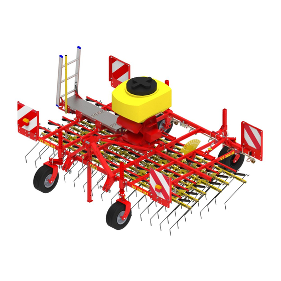
5.1 Intended use The Tined Weeder Pro VS 150 M1 or VS 300 M1 is designed and built for use in agricultural operations. Its tines penetrate in the soil and loosen it, and where applicable, remove any existing weeds. -
Page 7: General Safety-Related Instructions And Accident Prevention Regulations
The manufacturer is not liable for any damage resulting from unauthorised modifications and the use of components and auxiliary parts. 5.2 General safety-related instructions and accident prevention regulations The operator must read and understand this operating manual before using the harrow. ... -
Page 8: Mounted Implements
Working under the implement is forbidden. The implements must be checked regularly by the operator (before every use) for any fractures and cracks, chafe marks, leaks, loose bolts and connections, vibrations, unusual sounds, and to ensure they function correctly. ... -
Page 9: Tyres
The maintenance work itself may only be performed by trained specialist personnel and may never be performed alone. Extreme caution must be taken when changing defective components or tools. To reduce the risk of injuries, a clearly visible and legible sign "Caution: Maintenance work" must be placed during maintenance work. -
Page 10: Information Signs / Hazard Labels
Information signs / hazard labels Pay special attention to the stickers on the implement, as they warn you of specific dangers! 6.1 Information signs Standing in the danger Always lift the Read and observe the Do not stand on the zone (swivelling range) implement slowly off operating manual... -
Page 11: Hazard Labels
6.2 Hazard labels Do not stand between Do not climb onto Be careful with Caution, crushing area! the machines when rotating parts, use the escaping high-pressure Never reach into the connecting the intended access liquids! crushing danger zone implements and ladders! Observe the as long as the parts... -
Page 12: Safe Parking
7.2 Safe parking The parking surface must be suitable for parking the implement. The ground must be firm and level, so that the stands do not sink in and the harrow does not roll away. To ensure safe parking of the implement, lower the stands at the rear of the harrow. - Page 13 The higher the feeler wheels are moved up in the frame, the smaller the distance between the frame and the ground and the steeper the position of the tine ends relative to the ground. To set all of the feeler wheels, including those at the rear, to the same height, the same number of holes must be visible above the bracket.
-
Page 14: Hydraulic Tine Adjustment
7.5 Hydraulic tine adjustment The tines are adjusted with one hydraulic cylinder (VS 150 M1) or with two hydraulic cylinders connected in parallel (VS 300 M1). This allows the tine pre-tension to be changed while driving. All of the hydraulic cylinders (Figure 9) are connected by an oil circuit. -
Page 15: Maintenance And Care
4) The rotating feeler wheels to be used are inserted in the brackets. 5) When all of the rotating feeler wheels are installed at the desired positions, the Tined Weeder Pro is safely parked and uncoupled from the tractor according to 7.2. 6) In the next step, the headstock is dismounted. -
Page 16: Regular Maintenance Instructions
After cleaning, lubricate all of the grease points and distribute the grease evenly in the bearing points (e.g. perform a short test run). Do not use a high pressure cleaner to clean bearing and hydraulic parts. The paint can be damaged by cleaning with excessive pressure. ... -
Page 17: Changing The Springs
8.4 Changing the springs Overview: Diagram of the spring attachment 1: Plastic shell 2: Snap-fit 3: Fastening bolt Figure 16: Diagram of the spring attachment Step Unlock the snap-fits on one side of the spring assembly. To do so, press from the side in the hole in the spring assembly with a bolt or a pin (8 mm diameter) –... -
Page 18: Information On Nature Conservation And Environmental Protection
Information on nature conservation and environmental protection Reduction of noise pollution during use Any loose parts (e.g. chains) should be attached to prevent unnecessary noise. Energy-efficient use The tines of the Tined Weeder Pro should not penetrate into the soil deeper than necessary. By doing so, the towing vehicle is not unnecessarily strained and fuel can be saved. -
Page 19: Harrow Array Widths
Type designation: VS 150 M1 VS 300 M1 MDP 100 M1 CAUTION! The VS300 is more than 3 metres wide! When driving on public roads, the applicable country-specific regulations must be observed. 10.1 Harrow array widths VS 150 M1: VS 300 M1: Figure 20: Tine section width VS 150 M1 Figure 21: Tine section width VS 300 M1... -
Page 20: Combination Options For The Tined Weeder Pro With Pneumatic Seeders/Multi-Metering System
10.2 Combination options for the Tined Weeder Pro with pneumatic seeders/ Multi-Metering System PS 120 E PS 200 E PS 200 H PS 300 E PS 300 H PS 500 E PS 500 H MDP 100 Dimensions PS 90x60x80 100x70x90 100x70x110 110x80x100 110x80x115... -
Page 21: Hydraulic Diagram
Hydraulic diagram VS 150 M1 Figure 24 :Hydraulic diagram VS 150 M1 Tractor-side Coupling plug BG 2 Harrow-side Stop tap Tine adjustment locking block Control unit Double-acting cylinder for tine adjustment Coupling sleeve BG 2 Translation of the original operating manual Page 21... -
Page 22: Road Transport Of The Tined Weeder Pro
VS 300 M1 Figure 25: Hydraulic diagram VS 300 M1 Tractor-side Coupling plug BG 2 Harrow-side 2-way flow divider Tine adjustment locking block Control unit Stop tap Coupling sleeve BG 2 Double-acting cylinder for tine adjustment Road transport of the Tined Weeder Pro 12.1 Transport on public roads (in general) ... -
Page 23: Calculation Of The Weight Ratios For Axle Loads On The Tractor And Ballast Weights
Warning signs or stickers should be visible at a height of max. 150 cm above the road when driving. The bracket for the warning signs (additional equipment) is mounted on the centre frame (see section 16 Accessories). The axle load and the total weight of the towing vehicle may not be exceeded. - Page 24 This result is also entered in the table on the next page. Calculation of the actual front axle load T v tat If the required minimum front ballast (G ) is not reached with the front-mounted implement (G V min the weight of the front-mounted implement must be increased to the weight of the minimum front ballast! Now enter the calculated actual front axle load and the permissible front axle load specified in the...
-
Page 25: Lighting Circuit Diagram
Lighting circuit diagram Right 12 V plug, 7-pin Rear light, right Turn signal Rear light Brake light Left Rear light, left Brake light Rear light Turn signal Plug and cable assignment: No. Desig. Colour Function Yellow Turn signal, left White Earth Turn signal, Green... -
Page 26: Cropping Tips For Using The Tined Weeder Pro
Cropping tips for using the Tined Weeder Pro The Tined Weeder Pro's mode of action mainly consists of burying and uprooting the weeds and crumbling the soil surface. It also stimulates tillering in cereals. Compared to hoeing machines, the Tined Weeder Pro has two major benefits: It operates in a row-independent manner and has a comparatively high area efficiency. -
Page 27: Accessories
Accessories Tines with carbide coating To reduce tine wear, the VS 150 M1 / VS 300 M1 can be equipped with tines with carbide soldered on. Endurance tests show that these tines are worn much more slowly. This extends the service life of the tines until they need to be replaced considerably. - Page 28 Platform kit accessories kit For easier maintenance of the pneumatic seeder PS 120 - 200 M1 and multi-metering system MDP 100 M1, a suitable platform kit is available as an accessory. Please note that it must be mounted in compliance with ISO 4254-1. Item no.: 07027-2-017: platform kit accessories kit VS 150 M1 07028-2-013: platform kit accessories kit VS 300 M1...
-
Page 29: Spare Parts
Please keep your product number / serial number at hand. You can also view our online spare parts catalogue on our website www.apv.at the Service area. If you have any questions regarding spare parts or your order, our Customer Service (see point 3 for contact data) is also happy to assist you. - Page 30 Notes Page 30 Translation of the original operating manual...
- Page 31 Translation of the original operating manual Page 31...
- Page 32 +43 (0) 2913 / 8002 Web: www.apv.at Company details APV - Technische Produkte GmbH, Managing Director: Ing. Jürgen Schöls, Markus Alschner, Dallein 15 AT-3753 Hötzelsdorf, Austria, marketing@apv.at, www.apv.at, VAT ID no.: ATU 5067 1107 Photo credits: Company photos © APV Concept &...
Need help?
Do you have a question about the Tined Weeder Pro VS 150 M1 and is the answer not in the manual?
Questions and answers