Table of Contents

Related Manuals for APV TINED WEEDER PRO VS 470 M1


Summary of Contents for APV TINED WEEDER PRO VS 470 M1
- Page 1 TINED WEEDER PRO VS 470 M1, VS 600 M1, VS 750 M1, VS 900 M1, VS 1200 M1 OPERATING MANUAL PLEASE READ CAREFULLY BEFORE INITIAL OPERATION Translation of the original operating instructions Version: 2.0 EN; item number: 00602-3-742...
-
Page 2: Table Of Contents
TABLE OF CONTENTS EC DECLARATION OF CONFORMITY ..................4 UK CONFORMITY ASSESSED ...................... 5 IDENTIFICATION OF THE IMPLEMENT ..................6 SERVICE ............................6 WARRANTY ........................... 7 Warranty activation ......................7 SAFETY INFORMATION ........................ 7 Intended use ........................7 General safety-related instructions and accident prevention regulations ......8 Mounted implements ...................... - Page 3 13.2 Calculation of the weight ratios for axle loads on the tractor and ballast weights ....27 13.3 Table for the weight ratios ....................29 LIGHTING CIRCUIT DIAGRAM ....................29 DECOMMISSIONING, STORAGE AND DISPOSAL..............30 15.1 Decommissioning the implement ..................30 15.2 Storage of the implement ....................
-
Page 4: Ec Declaration Of Conformity
This declaration loses its validity if there are any changes to the mounted implement that are not approved by APV-Technische Produkte GmbH. Designation of the mounted implement model series: TINED WEEDER PRO VS 470 M1 TINED WEEDER PRO VS 600 M1 TINED WEEDER PRO VS 750 M1... -
Page 5: Conformity Assessed
This declaration loses its validity if there are any changes to the mounted implement that are not approved by APV-Technische Produkte GmbH. Designation of the mounted implement model series: TINED WEEDER PRO VS 470 M1 TINED WEEDER PRO VS 600 M1 TINED WEEDER PRO VS 750 M1... -
Page 6: Identification Of The Implement
For questions regarding spare parts To order maintenance and repair work Service address: APV – Technische Produkte GmbH Telephone: +43 2913 8001-5500 Zentrale: Dallein 15 Fax: +43 2913 8002 A-3753 Hötzelsdorf Email: service@apv.at AUSTRIA... -
Page 7: Warranty
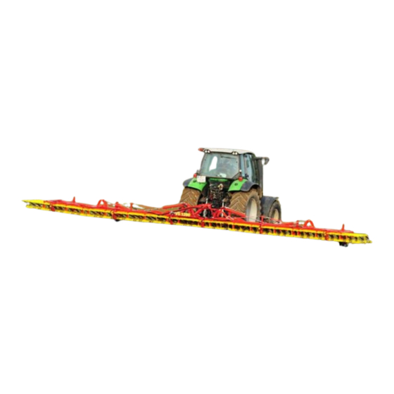
INTENDED USE The Tined Weeder Pro VS 470 M1 to VS 1200 M1 is designed and built for use in agricultural operations. Its tines penetrate in the soil and loosen it, and where applicable, remove any existing weeds. -
Page 8: General Safety-Related Instructions And Accident Prevention Regulations
The implement may not be folded when the tines are pre-tensioned. When the tines are set down on the ground, the pre-tension may not be reduced when the implement is at a standstill. This is not a problem while driving forwards. Intended use also includes compliance with the conditions for operation, maintenance, and repairs prescribed by the manufacturer. -
Page 9: Mounted Implements
Transport equipment - e.g. lighting, warning signs and any protective equipment, must be checked and mounted! Never leave the driver's platform while driving! The driving behaviour, steering and braking capacity are affected by mounted or towed implements and ballast weights. -
Page 10: Hydraulic System
Mounting of any sort of accessories onto the implement must be performed according to standards. The maximum permitted total weight may not be exceeded. Only APV implements and accessories may be mounted on the implement. Accessories must be mounted in compliance with the standards by qualified specialist personnel from an authorised company. -
Page 11: Tyres
It is strictly forbidden to stand on the platform or its access ladder while driving. When not in use, the ladder must be folded up and secured. An ascent must be established conforming to the standards. This ascent is available from APV. 6.7.1 FILLING THE SEEDER ... -
Page 12: Information Signs / Hazard Labels
INFORMATION SIGNS / HAZARD LABELS Pay special attention to the stickers on the implement, as they warn you of specific dangers! INFORMATION SIGNS Standing in the danger Always lift the Read and observe the Do not stand on the zone (swivelling range) implement slowly off operating manual before implement while... -
Page 13: Hazard Labels
HAZARD LABELS Caution, crushing area! Never reach into the crushing danger zone as long as the parts can still move! OPERATING INSTRUCTIONS MOUNTING ON THE TRACTOR Under difficult operating conditions, additional wheel weights can be useful. Please also refer to the operating manual from the tractor manufacturer. -
Page 14: Safe Parking
SAFE PARKING The parking surface must be suitable for parking the implement. The ground must be firm and level, so that the stands do not sink in and the harrow does not roll away. To ensure safe parking of the implement, lower the stands at the rear of the harrow. -
Page 15: Working Position And Setting The Working Depth
PLEASE NOTE! The tines may be pre-tensioned only when the Tined Weeder Pro is unfolded. During the folding procedure, first the outer side frame is folded by 180° onto the inner frame, which is then folded up by 90°. If the implement is unfolded into working position, the hydraulic control units and/or the double-acting hydraulic control units must be moved to the "N - neutral"... -
Page 16: Hydraulic Tine Adjustment
NOTE! When the feeler wheels are moved further down, the clearance is increased and the tine angle becomes steeper, and therefore more aggressive. The tine pressure remains the same. NOTE! Ideally, there should almost be a right angle (90° - 100°) between the wearing end of the tine and the soil (see Figure 12 - centre). -
Page 17: Additional Adjustment Options For Ground Adaptation
Figure 13: Hydraulic cylinder Figure 14: Flow divider on the centre frame ADDITIONAL ADJUSTMENT OPTIONS FOR GROUND ADAPTATION The slot in the cylinder working point on the side frame further improves the ground adaptation of the Tined Weeder Pro. If the laterally bolted, folding locking plates are installed, the upward ground adaptation of the side frame is fully available, but the downward ground adaptation is limited. -
Page 18: Maintenance And Care
The manufacturer is not liable for any unauthorised modifications to the implement and the use of components and auxiliary parts on the implement that were not purchased from APV. Before every operation, check the hydraulic hose lines for wear, damage and ageing. Damaged or faulty parts must be immediately replaced. -
Page 19: Tine Change
NOTE! When the implement is lifted off of the ground, the two side wings of the frame should be pointing slightly down. If this is not the case or if the wings are pointing down too much, the stop bolts on the joint must be adjusted. -
Page 20: Spring Assembly With Bolted Fastening
1. Step: Unlock the snap-fits on one side of the spring assembly. To do so, press from the side in the hole in the spring assembly with a bolt or a pin (8 mm diameter) – as shown in Figure 20 – until the pins touch. -
Page 21: Repairs And Service
PLEASE NOTE! Only tighten the nut far enough so that the washers are resting on the spring assembly. In no case should a gap be produced between the half shells due to excessive tightening. REPAIRS AND SERVICE In case of failure or damage to the implement, please contact the manufacturer. The contact data can be found in chapter 4. -
Page 22: Harrow Array Widths
Type designation VS 470 M1 VS 600 M1 VS 750 M1 VS 900 M1 VS 1200 M1 Minimum tractor 44 / 60 44 / 60 51 / 70 63 / 85 74 / 100 performance [kW/HP] PS 120 M1 – PS 500 M2 (see Point 11.2) Can be equipped with 11.1 HARROW ARRAY WIDTHS VS470:... -
Page 23: Combination Options For The Tined Weeder Pro With Pneumatic Seeders (Ps)
11.2 COMBINATION OPTIONS FOR THE TINED WEEDER PRO WITH PNEUMATIC SEEDERS (PS) PS 120 E PS 200 E PS 200 H PS 300 E PS 300 H PS 500 E PS 500 H Dimensions PS 90x60x80 100x70x90 100x70x110 110x80x100 110x80x115 125x80x120 125x80x125 HxWxD [cm]... -
Page 24: Hydraulicdiagram
HYDRAULICDIAGRAM VS 470 M1, VS 600 M1 Figure 31: Hydraulic diagram VS 470 M1 and VS 600 M1 Tractor-side T-connection Implement-side 3-way flow divider Folding Locking block Tine adjustment Ball valve Control unit Double-acting cylinder for tine adjustment Coupling sleeve BG 2 Double-acting cylinder for folding Coupling plug BG 2... - Page 25 VS 750 M1 Figure 32: Hydraulic diagram VS 750 M1 Tractor-side T-connection Implement-side 3-way flow divider Folding Locking block Tine adjustment Ball valve Control unit Double-acting cylinder for tine adjustment Coupling sleeve BG 2 Double-acting cylinder for folding Coupling plug BG 2...
- Page 26 VS 900 M1 and VS 1200 M1 Figure 33: Hydraulic diagram VS 900 M1 and VS 1200 M1 Tractor-side 7-way flow divider Implement-side Locking block Folding Ball valve Tine adjustment Lift limiter Control unit Double-acting cylinder for folding, inside Coupling sleeve BG 2 10 Double-acting cylinder for tine adjustment Coupling plug BG 2 11 Double-acting cylinder for folding, outside...
-
Page 27: Road Transport Of The Tined Weeder Pro
ROAD TRANSPORT OF THE TINED WEEDER PRO 13.1 TRANSPORT ON PUBLIC ROADS (GENERAL INFORMATION) When driving on roads after field operation, the tine sections should be cleaned of harrowing residues (soil, grass, etc.). Comply with the road traffic regulations of your country's legislation. ... - Page 28 Specifications: Tractor net weight Front axle load of the empty tractor Rear axle load of the empty tractor Total weight of the rear-mounted implement Total weight of the front-mounted implement Distance from the centre of gravity of the front-mounted implement to the centre of the front axle Figure 36 Wheelbase of the tractor...
-
Page 29: Lighting Circuit Diagram
Tyre load capacity: Enter the doubled value (two tyres) for the permissible tyre load capacity (see e.g. tyre manufacturer documents) in the table under Point 13.3. PLEASE NOTE! The minimum ballast must be attached to the tractor as a mounted implement or ballast weight! The calculated values may not be higher than the permissible values! 13.3 TABLE FOR THE WEIGHT RATIOS Double the... -
Page 30: Decommissioning, Storage And Disposal
DECOMMISSIONING, STORAGE AND DISPOSAL 15.1 DECOMMISSIONING THE IMPLEMENT To ensure that the implement remains fully functional, even if it is out of operation for longer periods of time, it is important to take precautions for storage: To do so, observe Point 8.2. 15.2 STORAGE OF THE IMPLEMENT ... -
Page 31: Accessories
Important prerequisites are a level seedbed, sufficiently deep seed placement, uniform germination, loose soil surface, few tracks, and suitable weather conditions. A missed harrowing pass can NOT be performed at a later date. Harrowing does not have a lasting effect => several consecutive work passes must be coordinated. ... -
Page 32: Dispersion Plate Bracket Accessories Kit
17.3 DISPERSION PLATE BRACKET ACCESSORIES KIT This is used to mount the dispersion plates on the Tined Weeder Pro. Order number: 07032-2-029: Dispersion plate accessories kit for VS470 (contains 8 dispersion plate brackets) 07018-2-033: Dispersion plate accessories kit for VS 600 M1 (contains 8 dispersion plate brackets) ... -
Page 33: Gpsa Sensor Mounting Kit
17.6 GPSA SENSOR MOUNTING KIT In combination with a pneumatic seeder, this sensor can be used for speed- dependent seed application. Order number: 06001-2-064 Figure 43 17.7 TINED WEEDER PRO WHEEL SENSOR MOUNTING KIT In combination with a pneumatic seeder, this sensor can be used for speed- dependent seed application or to stop the seeding shaft of a pneumatic seeder when lifting the implement at the headlands. -
Page 34: Manual Tine Lifting
17.10 MANUAL TINE LIFTING With the manual tine lifting, individual tines can be lifted (see Figure 47), e.g. to avoid working in rows where the plants are already taller. As a result, the harrow can be optimally adjusted for crops grown on beds. Either the entire harrow can be equipped or any number of tine lifting mechanisms can be selected. -
Page 35: Protective Sticker For Ps500 Hopper
17.13 PROTECTIVE STICKER FOR PS500 HOPPER When a PS500 is mounted on the VS1200, the protective stickers are required to protect the hopper from damage during road transport. Order number: 07014-2-646 Figure 51 17.14 HALF-SIDE FOLDING ACCESSORIES KIT With an additional double-acting hydraulic control unit, the implement can be folded on one side. -
Page 36: Spare Parts
Please keep your product number / serial number at hand. You can also view our online spare parts catalogue on our website www.apv.at the Service area. If you have any questions regarding spare parts or your order, our Customer Service (see point 4 for contact data) is also happy to assist you. - Page 37 NOTES...
- Page 38 NOTES...
- Page 39 NOTES...
- Page 40 APV – Technische Produkte GmbH Zentrale: Dallein 15 AT - 3753 Hötzelsdorf Tel.: +43 2913 8001 Email: office@apv.at www.apv.at...
Need help?
Do you have a question about the TINED WEEDER PRO VS 470 M1 and is the answer not in the manual?
Questions and answers