
Related Manuals for GW Instek PPX Series


Summary of Contents for GW Instek PPX Series
- Page 1 Programmable High Precision DC Power Supply PPX Series USER MANUAL Rev. A ISO-9001 CERTIFIED MANUFACTURER...
- Page 2 This manual contains proprietary information, which is protected by copyright. All rights are reserved. No part of this manual may be photocopied, reproduced or translated to another language without prior written consent of Good Will company. The information in this manual was correct at the time of printing. However, Good Will continues to improve products and reserves the rights to change specification, equipment, and maintenance procedures at any time without notice.
-
Page 3: Table Of Contents
TABLE OF CONTENTS Table of Contents SAFETY INSTRUCTIONS ..........5 GETTING STARTED ............8 PPX Series Overview ......9 Appearance .......... 12 Theory of Operation ......20 OPERATION ..............30 Set Up ..........31 Menu Tree ..........40 Basic Operation ........46 Sequence Test ........ - Page 4 PPX Series User Manual COMMUNICATION INTERFACE ........178 Interface Configuration ...... 179 FAQ ................208 APPENDIX ..............210 PPX Factory Default Settings ....210 PPX Specifications ......213 PPX Dimensions ........ 218 Declaration of Conformity ....219 INDEX ................220...
-
Page 5: Safety Instructions
SAFETY INSTRUCTIONS AFETY INSTRUCTIONS This chapter contains important safety instructions that you must follow during operation and storage. Read the following before any operation to insure your safety and to keep the instrument in the best possible condition. Safety Symbols These safety symbols may appear in this manual or on the instrument. - Page 6 PPX Series User Manual Do not dispose electronic equipment as unsorted municipal waste. Please use a separate collection facility or contact the supplier from which this instrument was purchased. Safety Guidelines Do not place any heavy object on the PPX.
- Page 7 SAFETY INSTRUCTIONS Disconnect the power cord before cleaning. Cleaning the PPX Use a soft cloth dampened in a solution of mild detergent and water. Do not spray any liquid. Do not use chemicals containing harsh material such as benzene, toluene, xylene, and acetone. Location: Indoor, no direct sunlight, dust free, Operation ...
- Page 8 After going through the overview, please read the theory of operation to become familiar with the operating modes, protection modes and other safety considerations. PPX Series Overview ..........9 Series lineup ..................9 Main Features ..................9 Accessories ..................10 Appearance ............
-
Page 9: Getting Started
GETTING STARTED PPX Series Overview Series lineup The PPX series consists of 6 models, covering a number of different current, voltage and power capacities: Model name Operation Voltage Operation Current Rated Power PPX-1005 0-10V 0-5A PPX-2002 0-20V 0-2A PPX-2005 0-20V... -
Page 10: Accessories
PPX Series User Manual Remote sensing to compensate for voltage drop in load leads. Support K type thermocouple temperature measurement. With 4 measuring currents and Manual / Auto shift function. Built-in USB, RS-232/485 and LAN interface. ... - Page 11 GETTING STARTED Optional Part number Description Accessories GRA-441-J Rack for PPX (JIS) GRA-441-E Rack for PPX (EIA) GTL-205A Temperature probe adaptor with thermocouple K type GTL-246 USB Cable (USB 2.0 Type A- Type B Cable, GTL-258 GPIB Cable, 2000mm GTL-259 RS232 cable with DB9 connector to RJ45 GTL-260 RS485 cable with DB9 connector to RJ45...
-
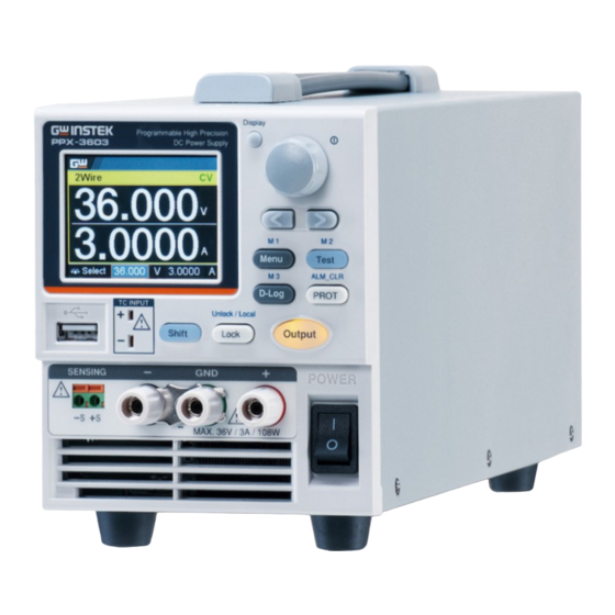
Page 12: Appearance
PPX Series User Manual Appearance Front Panel Used to switch among 4 different Display display modes. Button Used to navigate menu, and to Knob Key configure or confirm voltage/current/time values, among others. Also, the indicator on the upper-right corner shows current state... - Page 13 GETTING STARTED Used to select a parameter number in Left/Right the Function settings. Also the left Arrow Keys arrow key can be used as backspace. Used to enter the Menu page. Refer to Menu Button page 108 for detail. (+Shift) Used to recall the M1 setup. M1 Button Used to run customized test sequence.
- Page 14 PPX Series User Manual Used to lock all front panel buttons Lock Button other than the Output Button. Refer to page 60 for detail. (+Shift) Used to unlock the front panel Unlock/Local buttons or it switches to local mode. Button Used to turn the output on or off.
- Page 15 GETTING STARTED DC output terminal for PPX is Binding Posts Terminal or European Type Jack Terminal. PPX-1005 the max. output is 10V/5A/50W DC output terminal for PPX is Binding Posts Terminal or European Type Jack Terminal. PPX-2002 the max. output is 20V/2A/40W DC output terminal for PPX is Binding Posts...
-
Page 16: Display Area
PPX Series User Manual Display Area 2-wire or 4-wire indicator. 2Wire/4Wire Displays the voltage. Voltage Meter Displays the current. Current Meter The scrolling symbol indicates to select V/A Set between V and A set via scrolling knob key. Guidance When the external CC or CV control is External CC &... - Page 17 CV mode nor CC mode, it shows UR instead. If it is not under power output, it simply shows Off. When PPX series connects to LAN network, the 11. LAN Indicator icon will be shown.
-
Page 18: Rear Panel
PPX Series User Manual Rear Panel Remote-OUT RJ-45 connector that is used to daisy chain power supplies with the Remote-IN port to form a communication bus. Two different types of cables can be used for Remote-IN RS232 or RS485-based remote control. - Page 19 GETTING STARTED GPIB connector for units equipped with IEEE GPIB programming option. (Factory Installed Options) External analog remote control connector. EXT I/O AC inlet. Line Voltage Input The AC selector is located at the AC Select bottom side of the unit. Switch Switch Voltage to 100V, 120V, 220V or 240V.
-
Page 20: Theory Of Operation
PPX Series User Manual Theory of Operation The theory of operation chapter describes the basic principles of operation, protection modes and important considerations that must be taken into account before use. Operating Description The PPX power supplies are regulated DC... -
Page 21: Cc And Cv Mode
GETTING STARTED CC and CV Mode When the power supply is operating in CC and CV mode constant current mode (CC) a constant current Description will be supplied to the load. When in constant current mode the voltage output can vary, whilst the current remains constant. -
Page 22: Slew Rate
PPX Series User Manual Conversely the power supply will operate in CC mode when the load resistance is less than the critical resistance. In CC mode the current output is equal to I and the voltage output is less than V Crossover >R... -
Page 23: Bleeder Control
GETTING STARTED High Speed Priority Slew rate = mode Enabled Bleeder Control The PPX DC power supplies employ a bleed Background resistor in parallel with the output terminals. Bleed Load resistor Bleed resistors are designed to dissipate the power from the power supply filter capacitors when power is turned off and the load is disconnected. -
Page 24: Alarms
PPX Series User Manual By default the bleed resistance is on. For battery Note charging applications, be sure to turn the bleed resistance off as the bleed resistor can discharge the connected battery when the unit is off. Alarms The PPX power supplies have a number of protection features. -
Page 25: Considerations
GETTING STARTED Considerations The following situations should be taken into consideration when using the power supply. When the power supply switch is first turned Inrush current on, an inrush current is generated. Ensure there is enough power available for the power supply when first turned on, especially if a number of units are turned on at the same time. - Page 26 PPX Series User Manual Current limit level Measured Ammeter current When the power supply is connected to a Reverse Current: regenerative load such as a transformer or Regenerative load inverter, reverse current will feed back to the power supply. The PPX power supply cannot absorb reverse current.
- Page 27 GETTING STARTED When the power supply is connected to a load Reverse Current: such as a battery, reverse current may flow Accumulative energy. back to the power supply. To prevent damage to the power supply, use a reverse-current- protection diode in series between the power supply and load.
-
Page 28: Grounding
PPX Series User Manual Grounding The output terminals of the PPX power supplies are isolated with respect to the protective grounding terminal. The insulation capacity of the load, the load cables and other connected devices must be taken into consideration when connected to the protective ground or when floating. - Page 29 GETTING STARTED If the positive or negative terminal is connected Grounded output to the protective ground terminal, the terminal insulation capacity needed for the load and load cables is greatly reduced. The insulation capacity only needs to be greater than the maximum output voltage of the power supply with respect to ground.
- Page 30 PPX Series User Manual PERATION Set Up..............31 Power Up ...................31 Wire Gauge Considerations ............32 Output Terminals ................33 Connection with the front panel output terminal ..... 33 Using the Rack Mount Kit .............34 How to Use the Instrument ............34 Reset to Factory Default Settings ..........38 View System Version and Build Date ..........39...
-
Page 31: Operation
OPERATION Set Up Power Up Make sure that the power source is shut off. Background Use the AC power cable supplied with the product. 1. Connect the power cord to Steps the rear panel socket. Before connecting the power plug to Note an AC line outlet, make sure the voltage selector switches of the bottom... -
Page 32: Wire Gauge Considerations
PPX Series User Manual Wire Gauge Considerations Before connecting the output terminals to a Background load, the wire gauge of the cables should be considered. It is essential that the current capacity of the load cables is adequate. The rating of the cables must equal or exceed the maximum current rated output of the instrument. -
Page 33: Output Terminals
OPERATION Output Terminals Before connecting the output terminals to the Background load, first consider whether voltage sense will be used, the gauge of the cable wiring and the withstand voltage of the cables and load. Dangerous voltages. Ensure that the power to the WARNING instrument is disabled before handling the power supply output terminals. -
Page 34: Using The Rack Mount Kit
PPX Series User Manual Using the Rack Mount Kit The PPX series has an optional Rack Mount Kit Background (GW Instek part number: GRA-441-J [JIS], GRA-441-E [EIA]) that can be used to hold up to 4 PPX units into rack. - Page 35 OPERATION Use the knob key and arrow keys to set a Example 1 voltage of 10.100 volts. 1. From the main display, scroll knob key to move cursor to V Set field. 2. Click the knob key to enter the V Set field.
- Page 36 PPX Series User Manual 4. Click the knob key to confirm the input value setting (10.100). Use the knob key to enter Measurement Example 2 Average field and setting High option. Also, use the left arrow key to return to the previous page.
- Page 37 OPERATION 3. Click the knob key to enter the Measurement Average field followed by scrolling the knob key to select High option. 4. Click the knob key to confirm the High option for Measurement Average. 5. Click the left arrow key to return to the previous page –...
-
Page 38: Reset To Factory Default Settings
PPX Series User Manual Reset to Factory Default Settings The Recall Setup allows the PPX series to be Background reset back to the factory default settings. See page 210 for the default factory settings. 1. Press the Menu key to enter the Steps Menu page. -
Page 39: View System Version And Build Date
OPERATION View System Version The System Information allows you to view the Background PPX model name, serial number as well as firmware version. 1. Press the Menu key to enter the Steps Menu page. 2. Scroll the knob key to move to the Utility field followed by clicking the knob key to enter the Utility page. -
Page 40: Menu Tree
PPX Series User Manual Menu Tree Convention Use the menu trees as a handy reference for the power supply functions and properties. The PPX-1005/PPX- 2002/PPX-2005/PPX-3601/PPX-3603/PPX-10H01 menu system is arranged in a hierarchical tree. Each hierarchical level, which is coated in varied colors, can be navigated through the orders within the diagrams below. -
Page 41: Menu Page - 1
OPERATION Menu Page - 1 Level 1 Level 2 Level 3 Level 4 Menu Output Remote Sense V/I Slew Rate R_V Slew Rate F_V Slew Rate Output On Dly Output Off Dly 0 sec 0 sec 2 Wire CVHS 0.0001 V/ms 0.0001 V/ms (default by model) (default by model) -
Page 42: Menu Page - 2
PPX Series User Manual Menu Page - 2 Level 1 Level 2 Level 3 Level 4 Level 5 Menu Power On Config Return Power On Status Safe (default) Force Auto Constant PWR Control Power Return 110.2 W (default) (default by model) -
Page 43: Menu Page - 3
OPERATION Menu Page - 3 Level 1 Level 2 Level 3 Level 4 Level 5 Menu Utility System Information Model Serial Version Return Name Number Date & Time Year Month Hour Minute Save Return Keyboard Buzzer Bleeder Return Protect Keyboard Return Bleeder Return... -
Page 44: D-Log
PPX Series User Manual D-Log Level 1 Level 2 Level 3 Data Logger Type Sample Period Subfolder None 1.0 s 0000 (default) (default) (default) Save USB Send Remote PROT Level 1 Level 2 Level 3 Protect Voltage Limit OVP Level 0.000 V... -
Page 45: Test
OPERATION TEST Level 1 Level 2 Level 3 Level 4 Level 5 Test Sequence Total Step Cycle Number Cycle Start Cycle End None None None (load file) (load file) (load file) (load file) Sequence Edit Step Point Output Time Voltage Current OVP Level 2.00 s... -
Page 46: Basic Operation
PPX Series User Manual Basic Operation This section describes the basic operations required to operate the power supply. Setting OVP/OCP/UVL → from page 47 C.V. priority mode → from page 51 C.C. priority mode → from page 55 Display mode → page 59 Panel lock →... -
Page 47: Setting Ovp/Ocp/Uvl Levels
OPERATION Setting OVP/OCP/UVL Levels The OVP level and OCP level has a selectable Background range that is based on the output voltage and output current, respectively. The OVP and OCP level is set to the highest level by default. The actual selectable OVP and OCP range depends on the PPX model. - Page 48 PPX Series User Manual will no longer be able to set the output voltage to a value that is above about 95% of the OVP trip point or to a value that is lower than the UVL trip point. If...
- Page 49 OPERATION Setting Range Model 0.25~5.5 0.5~11 0~10.5 PPX-1005 0.1~2.2 1~22 0~21.0 PPX-2002 0.25~5.5 1~22 0~21.0 PPX-2005 0.05~1.1 1.8~39.6 0~37.8 PPX-3601 0.15~3.3 1.8~39.6 0~37.8 PPX-3603 PPX-10H01 0.05~1.1 5~110 0~105 The UVL setting range is from 0% ~ 105% of the rated Note output voltage.
- Page 50 PPX Series User Manual The OVP and OCP protection can Clear OVP/OCP be cleared after it has been tripped protection by clicking Shift key + ALM CLR key. The UVL protection On/Off depends on Voltage Limit. Note...
-
Page 51: Set To C.v. Priority Mode
OPERATION Set to C.V. Priority Mode When setting the power supply to constant voltage mode, a current limit must also be set to determine the crossover point. When the current exceeds the crossover point, the mode switches to C.C. mode. For details about C.V. operation, see page 21. C.C. - Page 52 PPX Series User Manual 3. Scroll the knob key to select between CVHS (CV High Speed Priority) and CVLS (CV Slew Rate Priority) options. CVHS = CV High Speed Priority Options CVLS = CV Slew Rate Priority 4. Press the knob key to save the selected option.
- Page 53 OPERATION 6. Scroll the knob key to adjust value, along with the arrow keys to change among digits followed by clicking the knob key to confirm set value, respectively. R_V Slew Rate / F_V Slew Rate Setting Range Model Max. Value Min.
- Page 54 PPX Series User Manual 9. Scroll the knob key to move to I (A) Set. Click knob key followed by scrolling knob key, along with the arrow keys to change among digits, to set the current limit (crossover point). Click knob key to confirm the set value.
-
Page 55: Set To C.c. Priority Mode
OPERATION Set to C.C. Priority Mode When setting the power supply to constant current mode, a voltage limit must also be set to determine the crossover point. When the voltage exceeds the crossover point, the mode switches to C.V. mode. For details about C.C. operation, see page 21. C.C. - Page 56 PPX Series User Manual 3. Scroll the knob key to select between CCHS (CC High Speed Priority) and CCLS (CC Slew Rate Priority) options. CCHS = CC High Speed Priority Options CCLS = CC Slew Rate Priority 4. Press the knob key to save the selected option.
- Page 57 OPERATION 6. Scroll the knob key to adjust value, along with the arrow keys to change among digits followed by clicking the knob key to confirm set value, respectively. R_C Slew Rate / F_C Slew Rate Setting Range Model Max. Value Min.
- Page 58 PPX Series User Manual 9. Scroll the knob key to move to I (A) Set. Click knob key followed by scrolling knob key, along with the arrow keys to change among digits, to set the current. Click knob key to confirm the set value.
-
Page 59: Display Modes
OPERATION Display Modes The PPX series power supplies allow you to view the output in 4 different modes: General (V/A), Power (V/A/W), Sequence (V/A/Sequence) or Temperature (V/A/T). 1. Press the Display key on main Steps screen to toggle among each mode. -
Page 60: Panel Lock
PPX Series User Manual Panel Lock The panel lock feature prevents settings from being changed accidentally. When activated, all keys including the knob key except the Shift key, Lock (Unlock/Local) key and Output key (if active) will be disabled. If the instrument is remotely controlled via the USB/LAN/GPIB interface, the panel lock is automatically enabled. -
Page 61: Save Setup
OPERATION Save Setup The PPX has up to 10 memory storage (M1 ~ M10) to save the set current, set voltage, OVP, OCP and ULV settings. 1. Press the Menu key to enter the Steps Menu page. 2. Scroll the knob key to move to the Save/Recall field followed by clicking the knob key to enter the Save/Recall page. -
Page 62: Recall Setup
PPX Series User Manual Recall Setup The PPX has up to 10 memory storage (M1 ~ M10) to recall the set current, set voltage, OVP, OCP and ULV settings. Also, it has 3 dedicated keys (M1, M2, M3) on front panel to promptly recall the setups. - Page 63 OPERATION When default is selected, the unit will restore Note back to the factory default setting. 1. Press the Shift key followed by M1 Recall Memory from front panel ~ M3 key on front panel to keys promptly recall the set setting. 2.
-
Page 64: Remote Sensing
PPX Series User Manual Remote Sensing Remote sense is used to compensate for the voltage drop seen across load cables due to the resistance inherent in the load cables. The remote sense terminals are connected to the load terminals to determine the voltage drop across the load cables. - Page 65 OPERATION 1. Connect the +S terminal to the positive Single Load potential of the load. Connect the -S terminal to the negative potential of the load. Load Output Input Output Input 2. Operate the instrument as normal. See the Basic Operation chapter for details.
-
Page 66: Temperature
PPX Series User Manual Temperature The PPX series can measure DUT temperature while power output simultaneously. Prior to temperature measurement, utilize the optional accessory GTL-205A, which includes a temperature probe adaptor with thermocouple K type, to connect between DUT and TC input on the front panel of PPX series. - Page 67 OPERATION 4. Scroll knob key to move to the Output Safe field, which is used to monitor temperature of DUT with user-defined threshold. The power output stops once threshold is met. Click knob key to enter the field followed by scrolling knob key to turn On/Off the function, along with the arrow keys to change among digits.
- Page 68 PPX Series User Manual °C -200.0 ~ 1372.0 Options °F -328.0 ~ 2501.6 6. Scroll knob key to move to the Adjust field, which acts like an user-defined offset value in accordance with environment factors by user preference. Click knob key to enter the field followed...
- Page 69 OPERATION On, Off Options When it is under V, A and Temperature display Temperature measurement mode, a thermometer icon appears in the status lower-left corner and varied colors of the icon represent different statuses as follows. Blue Temperature Control On with no GTL- 205A connected...
- Page 70 PPX Series User Manual The alarm of short circuit occurs from temperature measurement...
-
Page 71: Data Logger
OPERATION Data Logger The PPX series can save measured voltage, current and temperature data into either USB flash disk or send the data to program via remote control. 1. Press the D-Log key to enter the Steps Data Logger page. - Page 72 PPX Series User Manual 0000 ~ 9999 Range 4. Scroll the knob key to move to the Type field. Click knob key followed by scrolling it to select a type for data log saving. Click knob key to confirm setting.
- Page 73 OPERATION Dlog icon appears When the Save USB is selected, make sure that Note return to Data Logger page to select None for Type so that the latest data file can be saved properly. Owing to the fact that data log is being transmitted in real time via remote control, when the Send Remote is selected, there is no need to return to Data Logger page to select None for Type.
-
Page 74: Sequence Test
PPX Series User Manual Sequence Test This section describes how to use the Sequence function to edit, run, load and save sequence scripts for automated testing. The sequence function is useful if you want to perform a number of tests automatically. -
Page 75: Sequence Script File Format
OPERATION Sequence Script File Format The sequence script files are saved in the *.csv Background file format. When saving script file into internal memory, each file is saved as tXXX.csv where XXX is the file number from 001 to 010. When saving script file into the USB disk, each file is saved as S202_XXXX.csv where XXXX is the file serial number from 0001 to 9999. - Page 76 PPX Series User Manual It indicates infinite cycles. 1 ~ 1000000000 It sets cycle(s) from 1 to 1000000000 times. It sets which step is the starting step of cycle. Cycle Start The available steps options vary per total steps. Cycle Start...
-
Page 77: Sequence Step Edit Settings
(tXXX.csv). When there is any issue occurred from settings, Note PPX series will not be able to run sequence script. The error code along with warning message will be shown within the prompt message box when Run filed is enabled. - Page 78 PPX Series User Manual It sets a core action for select step. The available Point options are described as follows. Point Start It sets which step is the starting step of an entire sequence script. Be aware that this Start step can only be set equal to or earlier than the “Cycle...
- Page 79 OPERATION Log0 It sets which step will be executed in stop action for the data log function. This relates to the Log1 and Log2 actions as the following sections. Log1 It sets which step will be executed in the action of saving data log into USB disk.
- Page 80 PPX Series User Manual It sets over voltage protection setting for the OVP Level select step. OVP Level 5% ~ 110% rated voltage It sets over current protection setting for the OCP Level select step. OCP Level 5% ~ 110% rated current...
- Page 81 ON, OFF When there is any issue occurred from settings, Note PPX series will not be able to run sequence script. The error code along with warning message will be shown within the prompt message box when Run filed is enabled.
-
Page 82: Setting Sequence Script Configurations
PPX Series User Manual Setting Sequence Script Configurations 1. Press Test key followed by clicking Steps on Sequence field via knob key to enter the Sequence page. 2. Scroll knob key to move to the Total Step field followed by clicking knob key to enter the field. - Page 83 OPERATION 3. Scroll knob key to move to the Cycle Number field followed by clicking knob key to enter the field. Scroll knob key to adjust value along with arrow keys to change among digits followed by clicking knob key to confirm cycle number. Cycle Number INF, 1 ~ 1000000000 4.
- Page 84 PPX Series User Manual 5. Scroll knob key to move to the Cycle End field followed by clicking knob key to enter the field. Scroll knob key to adjust value along with arrow keys to change among digits followed by clicking knob key to confirm cycle end.
- Page 85 OPERATION 7. Scroll knob key to move to the Step field followed by clicking knob key to enter the field. Scroll knob key to select a step along with arrow keys to change among digits followed by clicking knob key to confirm the step to edit.
- Page 86 PPX Series User Manual 9. Scroll knob key to move to the Output field followed by clicking knob key to enter the field. Scroll knob key to turn on/off output followed by clicking knob key to confirm output action. Output ON, OFF 10.
- Page 87 OPERATION 11. Scroll knob key to move to the Voltage field followed by clicking knob key to enter the field. Scroll knob key to adjust value along with arrow keys to change among digits followed by clicking knob key to confirm voltage setting. Voltage 0V ~ 105% rated voltage 12.
- Page 88 PPX Series User Manual 13. Scroll knob key to move to the OVP Level field followed by clicking knob key to enter the field. Scroll knob key to adjust value along with arrow keys to change among digits followed by clicking knob key to confirm OVP setting.
- Page 89 OPERATION 15. Scroll knob key to move to the Bleeder field followed by clicking knob key to enter the field. Scroll knob key to turn on/off bleeder followed by clicking knob key to confirm bleeder action. Bleeder ON, OFF 16. Scroll knob key to move to the V/I Slew Rate field followed by clicking knob key to enter the field.
- Page 90 PPX Series User Manual When CVLS is selected in previous step, scroll knob key to R_V Slew Rate and F_V Slew Rate fields respectively followed by clicking knob key to enter each field. Scroll the knob key to adjust value,...
- Page 91 OPERATION 17. Scroll knob key to move to the Buzzer field followed by clicking knob key to enter the field. Scroll knob key to turn on/off buzzer followed by clicking knob key to confirm buzzer setting. Buzzer ON, OFF 18. Scroll knob key to move to the Measure Average field followed by clicking knob key to enter the field.
- Page 92 PPX Series User Manual 19. Scroll knob key to move to Jump To field followed by clicking knob key to enter the field. Scroll knob key to select a step number along with arrow keys to change among digits followed by clicking knob key to confirm step to jump to.
- Page 93 OPERATION 21. Scroll knob key to move to the Trigger Out field followed by clicking knob key to enter the field. Scroll knob key to turn on/off the function followed by clicking knob key to confirm the selection. Trigger Out ON, OFF 22.
-
Page 94: Run Sequence Script
PPX Series User Manual Run Sequence Script After well setting the relevant configurations Overview from Sequence and Sequence Edit pages, it is ready to launch a sequence script test. Also, it is available to load script from internal memory or the connected USB disk. See page 98 for how to load sequence script. - Page 95 OPERATION 4. Press the Test key to switch to display mode in which press Display key repeatedly until the V, A and Sequence mode is shown. The SEQ icon is displayed on the top banner accordingly. SEQ icon Sequence info section 5.
- Page 96 PPX Series User Manual SEQ pause in cycle SEQ pause mode Total step Ongoing cycle number Cycle Cycle Ongoing number start now step SEQ trigin in cycle SEQ trigin mode Total step Ongoing cycle number Cycle Cycle Ongoing number start...
- Page 97 OPERATION SEQ pause in jump mode pause Total step Ongoing now step SEQ trigin in jump mode trigin Total step Ongoing now step When a script is running, pressing the Output key Note will abort the execution of the script immediately. The Output key illumination will turn off.
-
Page 98: Load Sequence Script
A sequence script can be loaded from either Overview USB disk or internal memory. When USB disk is connected with PPX series, the script file in USB disk has higher priority over internal memory; that is, user can only load script file in USB disk when USB disk is plugged in. - Page 99 OPERATION 4. Scroll knob key to move to the Load field followed by clicking knob key to enter the field. Scroll knob key to select an available script from USB disk. (Format: S202_XXXX.csv). 5. The prompt window appears as follows. Click knob key to confirm loading the select script file.
- Page 100 PPX Series User Manual 2. Scroll knob key to move to the Load field followed by clicking knob key to enter the field. Scroll knob key to select an available script from internal memory (Format: tXXX.csv). 3. The prompt window appears as follows.
-
Page 101: Save Sequence Script
USB disk. Prior to saving script from USB disk, ensure the script file is placed in root directory. When saving script to USB disk, ensure USB disk is plugged into PPX series. 1. Press Test key followed by clicking Save script from... - Page 102 PPX Series User Manual 3. Click knob key to enter the Save From field followed by scrolling knob key to select Edit option. Click knob key again to confirm selection. 4. Scroll knob key to move to the Save To Internal field followed by clicking knob key to enter the field.
- Page 103 OPERATION 1. Insert a USB disk into the front panel Save script from USB-A port. Ensure the USB disk USB disk to internal memory contains a test script in root directory. 2. The icon of USB disk detection will be displayed on the upper status bar after a few seconds if the USB disk is recognized.
- Page 104 PPX Series User Manual 5. Click knob key to enter the Save From field followed by scrolling knob key to select a script file from USB disk (Format: S202_XXXX.csv). Click knob key to confirm selection. 6. Scroll knob key to move to the Save To Internal field followed by clicking knob key to enter the field.
- Page 105 OPERATION 1. Insert a USB disk into the front panel Save script from USB-A port. edited one to USB disk 2. The icon of USB disk detection will be displayed on the upper status bar after a few seconds if the USB disk is recognized. USB indicator 3.
- Page 106 PPX Series User Manual 5. Click knob key to enter the Save From field followed by scrolling knob key to select Edit option. Click knob key again to confirm selection. 6. Scroll knob key to move to the Save To USB field followed by clicking knob key to enter the field.
-
Page 107: Menu Configuration
MENU CONFIGURATION ENU CONFIGURATION Configuration Overview ........108 Output ............... 108 Measurement............. 112 EXT Control ............115 TRIG Control ............. 120 PWR On Config ..........126 Constant PWR ............ 127 Temperature ............130 Save/Recall ............134 Interface ............137 Utility ..............144 APP .............. -
Page 108: Configuration Overview
PPX Series User Manual Configuration Overview The MENU configuration of PPX series consists of Output setting, Measurement setting, EXT Control setting, TRIG Control setting, PWR On Config setting, Constant PWR setting, Temperature setting, Save/Recall setting, Interface setting, Utility setting, APP setting and Calibration setting. - Page 109 MENU CONFIGURATION 2. Click knob key to enter the Output page. Scroll knob key to move to Output On/Off Dly fields, respectively, followed by clicking knob key to enter each field. 3. Click arrow keys to move among each unit (h:m:s). Scroll knob key to change value followed by clicking the knob key to confirm the set value.
- Page 110 PPX Series User Manual 5. Scroll the knob key to select option followed by clicking the knob key to confirm the selection. 2 Wire, 4 Wire Remote Sense The C.V. and C.C. mode have two selectable V/I Slew Rate slew rates: High Speed Priority (CVHS, CCHS) and Slew Rate Priority (CVLS, CCLS).
- Page 111 MENU CONFIGURATION 8. When CVLS or CCLS is selected, scroll knob key to R_V Slew Rate or F_V Slew Rate fields followed by clicking knob key to enter the fields, respectively. 9. Scroll the knob key to adjust value, along with the arrow keys to change among digits followed by clicking the knob key to confirm set value, respectively.
-
Page 112: Measurement
PPX Series User Manual Measurement It sets the speed level of display sampling for Measure the measure average setting. More the average Average numbers (High), slower the display update. By contrast, the Off option indicates no sampling average and thus with the fastest speed in display update. - Page 113 MENU CONFIGURATION 3. Scroll knob key to change option followed by clicking the knob key to confirm the selection. High, Middle, Low, Off Measure Average It sets display range for voltage. Voltage Range 4. Scroll knob key to move to Voltage Range field followed by clicking knob key to enter the field.
- Page 114 PPX Series User Manual It sets display range for current. Current Range 6. Scroll knob key to move to Current Range field followed by clicking knob key to enter the field. 7. Scroll the knob key to select option followed by clicking the knob key to confirm the selection.
-
Page 115: Ext Control
MENU CONFIGURATION EXT Control By connecting with an external voltage or CV Control resistance control, it can output voltage in the Constant Voltage (CV) control. Both CV and CC controls can be enabled simultaneously. Before setting the EXT Control, ensure that: The output is off. - Page 116 PPX Series User Manual 3. Scroll knob key to select option followed by clicking the knob key to confirm the selection. CV Control Option Internal control for the CV range. Front External voltage control of the External V voltage output is performed by the EXT I/O connector.
- Page 117 MENU CONFIGURATION 4. Scroll knob key to move to CC Control field followed by clicking knob key to enter the field. 5. Scroll knob key to select option followed by clicking the knob key to confirm the selection. CC Control Option Internal control for the CC range.
- Page 118 PPX Series User Manual Via the pin 10 of EXT I/O connector, power Output Type output can be activated through either a high or low signal externally. Before setting the EXT Control, ensure that: The output is off. The load is not connected.
- Page 119 MENU CONFIGURATION Prior to external signal control, it is required to Output Enable turn On Output Enable so that power output can be activated via external high/low signal. Before setting the EXT Control, ensure that: The output is off. The load is not connected. 8.
-
Page 120: Trig Control
PPX Series User Manual TRIG Control It determines what signal (High or Low) will Trigin Level trigger the trigger-in action. Before setting the TRIG Control, ensure that: The output is off. The load is not connected. 1. Press the Menu key followed by scrolling knob key to move to TRIG Control field. - Page 121 MENU CONFIGURATION 3. Scroll knob key to select option followed by clicking the knob key to confirm the selection. High, Low Trigin Level To determine the ensuing action when trigger- Trigin Action in signal is received. 4. Scroll knob key to move to Trigin Action field followed by clicking knob key to enter the field.
- Page 122 PPX Series User Manual PPX will change to the predefined V/I Set V/I settings when trigger-in signal is received. It is required to set Trigin Voltage and Trigin Current, individually before enabling V/I Set. PPX will change to the predefined...
- Page 123 It determines what trigger-out signal (High or Trigout Level Low) will be transmitted after execution of predefined Trigout Source from PPX series. 8. Scroll knob key to move to Trigout Level field followed by clicking knob key to enter the field.
- Page 124 PPX Series User Manual High, Low Trigout Level To determine what source of action to launch Trigout Source the trigger-out signal. 10. Scroll knob key to move to Trigout Source field followed by clicking knob key to enter the field.
- Page 125 MENU CONFIGURATION 12. Scroll the knob key to move to the Trigout Width field followed by clicking knob key to enter the field. 13. Scroll knob key to adjust value, along with the arrow keys to change among digits. Click knob key again to confirm set value.
-
Page 126: Pwr On Config
PPX Series User Manual PWR On Config It determines power output On or Off when Power On Status PPX unit is starting up. Safe: Output Off at startup. Force: Output On at startup. Auto: Output follows the previous status. -
Page 127: Constant Pwr
MENU CONFIGURATION Constant PWR To turn On or Off the Constant PWR function, Control which indicates the output power watt(s) will be fixed in the set value. 1. Press the Menu key followed by scrolling knob key to move to Constant PWR field. - Page 128 PPX Series User Manual To determine the fixed output power value for Power Constant PWR function. 4. Scroll knob key to move to Power field followed by clicking knob key to enter the field. 5. Scroll the knob key to adjust value,...
- Page 129 MENU CONFIGURATION 6. Under the Power (V/A/W) display mode, scroll knob key to move among V Set, I Set and CP fields followed by clicking knob key enter each field, respectively. 7. Scroll knob key to CP field followed by click knob key to enter the field.
-
Page 130: Temperature
PPX Series User Manual Temperature To turn On or Off the Temperature function, Control which measures temperature of DUT while powering output simultaneously. This function requires the affiliated accessory. Refer to page 66 for more details. 1. Press the Menu key followed by scrolling knob key to move to Temperature field. - Page 131 MENU CONFIGURATION 3. Scroll knob key to turn On or Off the function by clicking the knob key to confirm the setting. On, Off Control To determine the Temperature unit for display. Unit 4. Scroll knob key to move to Unit field followed by clicking knob key to enter the field.
- Page 132 PPX Series User Manual 6. Scroll knob key to move to the Output Safe field followed by clicking knob key to enter the field. 7. Scroll knob key to turn On/Off the function. Click knob key again to confirm. On, Off...
- Page 133 MENU CONFIGURATION 9. Scroll knob key to set monitor value, along with the arrow keys to change among digits. Click knob key again to confirm. °C -200.0 ~ 1372.0 Options °F -328.0 ~ 2501.6 To set an offset value for temperature Adjust measurement in accordance with environment factors by user preference.
-
Page 134: Save/Recall
PPX Series User Manual Save/Recall Up to 10 memory setups (M1~M10) can be Save Mem Set saved to the internal storage. 1. Press the Menu key followed by scrolling knob key to move to Save/Recall field. 2. Click knob key to enter the Save/Recall page. - Page 135 MENU CONFIGURATION 3. Scroll knob key to select an option followed by clicking the knob key to confirm the selection. Scroll knob key to move to OK followed by clicking knob key again to confirm save. M1 ~ M10 Save Mem Set Up to 10 memory setups (M1~M10) can be Recall Mem Set recalled from the internal storage...
- Page 136 PPX Series User Manual 5. Scroll knob key to select an option followed by clicking the knob key to confirm the selection. Scroll knob key to move to OK followed by clicking knob key again to confirm recall. M1~M10 From the internal Recall memory M1 ~ M10.
-
Page 137: Interface
MENU CONFIGURATION Interface The PPX series use the IN & OUT ports for UART UART communication coupled with RS232 or RS485 adapters. 1. Press the Menu key followed by scrolling knob key to move to Interface field. 2. Click knob key to enter the Interface page. - Page 138 Also, it is available to return by clicking the left arrow key. The PPX series use the Ethernet LAN (Local Area Network) port for a number of different applications. Ethernet can be configured for basic remote control or monitoring using a web server or it can be configured as a socket server.
- Page 139 MENU CONFIGURATION 5. Scroll knob key to move to LAN field followed by click knob key to enter the LAN page. 6. There are several relevant settings for LAN interface as following details. Use knob key to scroll and click to configure each setting.
- Page 140 PPX Series User Manual Sets the subnet mask. The subnet mask is split Subnet Mask into four parts. 0~255, 0~255, 0~255, 0~255 Sets the gateway address. The gateway address Gateway IP is split into 4 parts. 0~255, 0~255, 0~255, 0~255 Sets the DNS address.
- Page 141 Also, it is available to return by clicking the left arrow key. The PPX series use the GPIB connector for basic GPIB remote control. 11. Scroll knob key to move to GPIB field followed by click knob key to enter the GPIB page.
- Page 142 Also, it is available to return by clicking the left arrow key. The PPX series use the USB B-type port for basic remote control. 14. Scroll knob key to move to USB field followed by click knob key to enter the USB page.
- Page 143 Also, it is available to return by clicking the left arrow key. Sets PPX series as a web server. Enter the IP Web Server address of PPX series in a web browser to establish connection.
-
Page 144: Utility
PPX Series User Manual Utility The system information including Model System Name, Serial Number as well as Version of PPX Information series are shown in this section. 1. Press the Menu key followed by scrolling knob key to move to Utility field. - Page 145 Also, it is available to return by clicking the left arrow key. The system time of PPX series can be Date & Time configured within this section. 5. Scroll knob key to move to Date &...
- Page 146 PPX Series User Manual To configure month field. Month To configure day field. To configure hour field. Hour To configure minute field. Minute To save the configured system time. Save 7. Scroll knob key to move to Return field followed by clicking knob key to return back to the previous page.
- Page 147 MENU CONFIGURATION 9. There is only a Lock Mode field for Keyboard setting as the following detail. Use knob key to scroll and click to configure Lock Mode setting. Output On/Off Power output can be Lock Mode turned On/Off when lock mode is activated.
- Page 148 PPX Series User Manual 12. There are two relevant settings for Buzzer setting as following details. Use knob key to scroll and click to configure each setting. To turn On or Off the buzzer sound for Protect protection alarm. On, Off...
- Page 149 Also, it is available to return by clicking the left arrow key. While operating PPX series via remote control, it Communication Monitor is convenient to enable Communication Monitor...
- Page 150 PPX Series User Manual 17. Scroll knob key to move to Communication Monitor field followed by click knob key to enter the Communication Monitor page. 18. There are two settings for Communication Monitor page as following details. Use knob key to scroll and click to configure the setting.
- Page 151 MENU CONFIGURATION Communicati The icon indicates Communication Monitor is activated on Monitor Display...
-
Page 152: App
PPX Series User Manual The APP (application) field is the extending License function for future update when license file is available. It is required to insert the USB disk in which the license file is stored into the PPX series beforehand. Contact your dealer for the necessary license file. - Page 153 MENU CONFIGURATION 3. Click knob key to enter the Install File field followed by importing the license file from the USB disk for installation. 4. Scroll knob key to move to Return field followed by clicking knob key to return back to the previous page. Also, it is available to return by clicking the left arrow key.
- Page 154 PPX Series User Manual 6. There are few settings for AH/WH Meter page as following details. Use knob key to scroll and click to configure the setting. Also, use arrow keys to move among digits when available. It sets alarm for either Ahour or Whour Mode function from the APP display mode.
-
Page 155: Calibration
MENU CONFIGURATION Calibration The Calibration section is used to access to the System Update calibration function, which requires a password to enter the menu. Please see your distributor or dealer for details when necessary. -
Page 156: Analog Control
PPX Series User Manual NALOG CONTROL The Analog Control chapter describes how to control the voltage or current output using an external voltage or resistance, monitor the voltage or current output as well as remotely turning off the output or shutting down the power supply. -
Page 157: Analog Remote Control Overview
ANALOG CONTROL Analog Remote Control Overview The PPX power supply series have a number of analog control options. The Analog Control connectors are used to control output voltage and current using external voltage or resistance. The power supply output can also be controlled using external switches. Analog control connector overview →... - Page 158 PPX Series User Manual Analog Control Connector Overview The EXT I/O Connector is a 20pin connector Overview that can be used with the plug for wiring connection. The connector is used for all analog remote control. The pins used determine what remote control mode is used.
- Page 159 ANALOG CONTROL 6 This is the common line for external signal pins A COM 1, 2, 3, and 5. 7 Not connected. N.C. 8 Not connected. N.C. 9 Output on/off line. OUT ON/OFF On when set to a low TTL signal, Off when set CONT to a high TTL signal.
-
Page 160: External Voltage Control Of Voltage Output
PPX Series User Manual 19 On when a protection function (OVP, OCP, Alarm Status OTP, AC ALARM) has been activated or when an output shutdown signal is being applied (open-collector photocoupler output).1 20 This is the common line for the status signal Status COM pins 2 to 6. - Page 161 ANALOG CONTROL When connecting the external voltage source to Connection the analog connector, use shielded or twisted paired wiring. EXT-V + Analog connector - 2 core shielded wire or twisted Output pair Terminal Pin3 → EXT-V (+) Pin4 → EXT-V (-) Wire shield →...
- Page 162 PPX Series User Manual 1. Connect the external voltage according to the Panel operation connection diagrams above. 2. Set the CV Control as External V. Page 108 Also, set Output Type per application and turn On Output Enable. 3. Press the Output key. The voltage can now be controlled with the External voltage.
-
Page 163: External Voltage Control Of Current Output
ANALOG CONTROL External Voltage Control of Current Output External voltage control of the current output is Background accomplished using the analog control connector on the rear panel. A voltage of 0~10V is used to control the full scale current of the instrument, where: Output current = full scale current ×... - Page 164 PPX Series User Manual If the wire shield needs to be grounded at the Connection- alt. voltage source (EXT-V), then the shield cannot shielding also be grounded at the negative (-) terminal output of the PPX power supply. This would short the output.
- Page 165 ANALOG CONTROL The input impedance for external voltage control is Note a high impedance OPA input. A COM Use a stable voltage supply for the external voltage control. CV and CC Slew Rate Priority (CVLS, CCLS) are Note disabled when using external voltage control. See the CVLS and CCLS Settings on page 51 &...
-
Page 166: External Resistance Control Of Voltage Output
PPX Series User Manual External Resistance Control of Voltage Output External resistance control of the voltage output Background is accomplished using the analog connector on the rear panel. A resistance of 0Ω~10kΩ is used to control the full scale voltage of the instrument. -
Page 167: External Resistance Control Of Current Output
ANALOG CONTROL 3. Press the Output key. The voltage can now be controlled with the External resistance. Ensure the resistor(s) and cables used exceed the Note isolation voltage of the power supply. For example: insulation tubes with a withstand voltage higher than the power supply can be used. - Page 168 PPX Series User Manual Connection EXT-R Analog connector 2 core shielded wire or twisted Output pair Terminal Pin5 → EXT-R Pin6 → EXT-R Wire shield → negative (-) output terminal 1. Connect the external resistance according to the Steps connection diagrams above.
-
Page 169: External Control Of Output
ANALOG CONTROL External Control of Output The output can be turned on or off externally Background using a switch. The analog control connector can be set to turn the output on from a high or low signal. The voltage across pins 9 and 12 are internally pulled to +5V with 2kΩ... - Page 170 PPX Series User Manual 3. The switch is now ready to set the output on or off. When using a switch over long distances, please Note use a switch relay to extend the line from the coil side of the relay.
-
Page 171: External Trigger In / Out
ANALOG CONTROL External Trigger In / Out Pin 10 is used for the external trigger input and Background pin 11 is used as the trigger output. Pin 12 is the B common for both pins. The trigger input can be configured to perform an action such as toggling the output on/off, load a memory setting or apply a voltage/current setting when a trigger is... - Page 172 PPX Series User Manual Schematic B COM Trigger 100kΩ input signal Analog connector B COM...
-
Page 173: Remote Monitoring
ANALOG CONTROL Remote Monitoring The PPX power supplies have remote monitoring support for current and voltage output. They also support monitoring of operation and alarm status. External monitoring of output voltage and current → from page 173 External monitoring of operation mode and alarm status → from page 175 External Voltage and Current Monitoring The analog connector is used to monitor the Background... - Page 174 PPX Series User Manual IMON Connection Analog connector I MON → Output Terminal Pin4 → Neg (-) Pin1 → Pos (+) Maximum output impedance is 10KΩ. Ensure the Note sensing circuit has an input impedance greater than 1MΩ. The monitor outputs are strictly DC and should not be used to monitor analog components such as transient voltage response or ripple etc.
-
Page 175: External Operation And Status Monitoring
ANALOG CONTROL External Operation and Status Monitoring The analog connector can also be used to Background monitor the status operation and alarm status of the instrument. The pins are isolated from the power supply internal circuitry by photo couplers. Status Com (Pin 20) is a photo coupler emitter output, whilst pins 15~19 are photo coupler collector outputs. - Page 176 PPX Series User Manual This is the common line for the Status COM status signal pins 15 to 19. Schematic Pins 15, 16, 17, 18, 19 20 (Status COM1) Below are 4 example timing diagrams covering Timing diagrams a number of scenarios. Note that pins 15~19 are all active low.
- Page 177 ANALOG CONTROL The diagram below shows the timing diagram CC MODE: when the output is turned on when the PPX is Output turned on set to CC mode. CV status CC status Output status The diagram below shows the output status CC MODE: lines when the output is turned off in CC mode.
- Page 178 PPX Series User Manual OMMUNICATION INTERFACE This chapter describes basic configuration of IEEE488.2 based remote control. For a command list, refer to the programming manual, downloadable from GW Instek website, www.gwinstek.com Interface Configuration ........179 USB Remote Interface ..............179 Configuration ....................
-
Page 179: Communication Interface
COMMUNICATION INTERFACE Interface Configuration USB Remote Interface Configuration Type A, host PC side connector Configuration Rear panel Type B, slave PPX side connector 1.1 (full speed) Speed CDC (communications device USB Class class) 1. Connect the USB cable to the rear Steps panel USB B port. -
Page 180: Usb Cdc Function Check
PPX Series User Manual USB CDC Function Check To test the USB CDC functionality, National Background Instruments Measurement and Automation Explorer can be used. This program is available on the NI website, www.ni.com., via a search for the VISA Run-time Engine page, or “downloads”... - Page 181 COMMUNICATION INTERFACE 4. The Device Manager will show up CDC- WXXXXXX on “Other Devices”. 5. Select the CDC-WXXXXXX and click the right button of mouse to "Update Driver Software".
- Page 182 7. Indicate the driver folder to the system and then press "Next". And this folder should consist of below 2 files. The USB driver of PPX can be downloaded from Note download area of PPX on the GW Instek website http://www.gwinstek.com/en- global/Support/download...
- Page 183 COMMUNICATION INTERFACE 8. Windows 7 will install the driver for a while. 9. If everything works fine, you may get below message. And the COM53 is the USB CDC ACM port of PPX.
- Page 184 PPX Series User Manual 10. Double check the "Device Manager". The port should like below. Steps 1~10 are for the USB CDC Driver installation. 11. Start the NI Measurement and Automation Explorer (MAX) program. Using Windows, press: Start>All Programs>National Instruments>Measurement & Automation...
- Page 185 COMMUNICATION INTERFACE 12. From the Configuration panel access; My System>Devices and Interfaces>Network Devices 13. Click Open VISA Test Panel. 14. Click the Configuration icon, 15. Click on I/O Settings. 16. Make sure the Enable Termination Character check box is checked, and the terminal character is \n (Value: xA).
- Page 186 PPX Series User Manual 21. The *IDN? query will return the Manufacturer, model name, serial number and firmware version in the dialog box. GW-INSTEK,PPX-10H01,TW123456,V0.A4...
-
Page 187: Gpib Remote Interface
COMMUNICATION INTERFACE GPIB Remote Interface Configuration To use GPIB, the optional GPIB option (GW Instek part number: Option 1) must be installed. This is a factory installed option and cannot be installed by the end-user. Only one GPIB address can be used at a time. -
Page 188: Gpib Function Check
PPX Series User Manual GPIB Function Check To test the GPIB functionality, National Background Instruments Measurement and Automation Explorer can be used. This program is available on the NI website, www.ni.com., via a search for the VISA Run-time Engine page, or “downloads”... - Page 189 COMMUNICATION INTERFACE 4. Select the device (GPIB address of PPX) that now appears in the System>Devices and Interfaces > GPIB-USB-HS “GPIBX” node. 5. Click on the VISA Properties tab on the bottom. 6. Click Open Visa Test Panel.
- Page 190 PPX Series User Manual 7. Click on Configuration. 8. Click on the GPIB Settings tab and confirm that the GPIB settings are correct. 9. Click on the I/O Settings tab. 10. Make sure the Enable Termination Character check box is checked, and the terminal character is \n (Value: xA).
- Page 191 COMMUNICATION INTERFACE 12. Click on Input/Output. 13. Click on the Basic I/O tab. 14. Enter *IDN? in the Select or Enter Command drop down box. 15. Click Query. 16. The *IDN? query will return the Manufacturer, model name, serial number and firmware version in the dialog box.
-
Page 192: Uart Remote Interface
PPX Series User Manual For further details, please see the programming Note manual, available on the GW Instek web site @ www.gwinstek.com. UART Remote Interface Configure UART The PPX uses the IN & OUT ports for UART Overview communication coupled with RS232 (GW Instek part number: GTL-259) or RS485 adapters (GW Instek part number: GTL-260). - Page 193 COMMUNICATION INTERFACE RS485 cable with DB-9 Connector Remote IN Port Remarks DB9 & RJ-45 Pin No. Name Pin No. Name shielded Housing Shield Housing Shield connectors from GTL-260 TXD - RXD - Twisted connection kit pair TXD + RXD + RXD - TXD - Twisted...
-
Page 194: Uart Function Check
PPX Series User Manual 3. The indicator will be shown when a remote connection has been established. Remote Control indicator UART Function Check Invoke a terminal application such as Realterm. Functionality check To check the COM port No., see the Device... - Page 195 COMMUNICATION INTERFACE For further details, please see the programming Note manual, available on the GW Instek web site @ www.gwinstek.com.
-
Page 196: Multi Unit Connection
PPX Series User Manual Multiple Unit Connection The PPX power supplies can have up to 31 units daisy-chained together using the 8 pin connectors (IN OUT ports) on the rear panel. The first unit in the chain is remotely connected to a PC using GTL-260 (RS485 cable with DB9 connector).Each subsequent... -
Page 197: Multiple Units Function Check
COMMUNICATION INTERFACE 4. Set the addresses and mode of all units using UART menu. It must be a unique address identifier and mode select is RS485. 5. Multiple units can be operated using SCPI commands now. See the programming manual or see the function check below for usage details. - Page 198 The power supply acknowledges received commands by returning an “OK” message. If an error is detected the power supply will return an error message. For further details, please see the programming manual, available on the GW Instek web site @ www.gwinstek.com.
-
Page 199: Configure Ethernet Connection
The PPX series supports both DHCP connections so the instrument can be automatically connected to an existing network or alternatively, network settings can be manually configured. -
Page 200: Web Server Remote Control Function Check
PPX Series User Manual 2. Turn On DHCP and Web Server Page 138 & settings. 3. The indicator will be shown when a remote connection has been established. Remote Control indicator It may be necessary to cycle the power or refresh Note the web browser to connect to a network. - Page 201 COMMUNICATION INTERFACE The web browser interface appears as follows. The web browser interface allows you to access the following: Network configuration settings Measurement setting Normal Function setting External Control setting Temperature Control setting Analog Control ...
-
Page 202: Sockets Server Configuration
PPX Series User Manual Sockets Server Configuration This configuration example will configure the Configuration PPX socket server. The following configuration settings will manually assign the PPX an IP address and enable the socket server. The socket server port number is fixed at 2268. -
Page 203: Socket Server Function Check
COMMUNICATION INTERFACE Socket Server Function Check To test the socket server functionality, National Background Instruments Measurement and Automation Explorer can be used. This program is available on the NI website, www.ni.com., via a search for the VISA Run-time Engine page, or “downloads”... - Page 204 PPX Series User Manual 4. Select Manual Entry of Raw Socket from the popup window. 5. Enter the IP address and the port number of the PPX. The port number is fixed at 2268. 6. Click the Validate button. 7. A popup will appear if a connection is successfully established.
- Page 205 COMMUNICATION INTERFACE 9. Next configure the Alias (name) of the PPX connection. In this example the Alias is: PPX_DC1 10. Click finish. 11. The IP address of the PPX will now appear under Network Devices in the configuration panel. Select this icon now.
- Page 206 PPX Series User Manual 12. Click Open VISA Test Panel. 13. Click the Configuration icon, 14. Click on I/O Settings. 15. Make sure the Enable Termination Character check box is checked, and the terminal character is \n (Value: xA). 16. Click Apply Changes.
- Page 207 COMMUNICATION INTERFACE 20. The *IDN? query will return the Manufacturer, model name, serial number and firmware version in the dialog box. GW-INSTEK,PPX-10H01,TW123456,V0.A4 For further details, please see the programming Note manual, available on the GW Instek web site @ www.gwinstek.com.
-
Page 208: Faq
PPX Series User Manual • How often should the power supply be calibrated? • The OVP voltage is triggered earlier than expected. • Can I combine more than 1 cable together for the output wiring? • The accuracy does not match the specification. - Page 209 The accuracy does not match the specification. Make sure the device is powered On for at least 30 minutes, within 23℃±5℃. This is necessary to stabilize the unit to match the specification. For more information, contact your local dealer or GWInstek at www.gwinstek.com / marketing@goodwill.com.tw.
-
Page 210: Appendix
PPX Series User Manual PPENDIX PPX Factory Default Settings The following default settings are the factory configuration settings for the power supply. For details on how to return to factory default settings, see page 62. Initial Default Setting Output LOCK... - Page 211 APPENDIX EXT (External) Control Default Setting CV Control Front Panel CC Control Front Panel Output Type High Output Enable TRIG(Trigger Control) Default Setting Trigin Level High Trigin Action None Trigin Voltage 0.000 V Trigin Current 0.0000 A Trigin Memory Trigout Level Trigout Source None Trigout Width...
- Page 212 PPX Series User Manual Utility - Bleeder Default Setting Bleeder APP - AH/WH Meter (License Key) Default Setting Mode Disable AHour 999999999.999 Ah WHour 999999999.999 Wh Protect Default Setting Voltage Limit 0.000 V OVP Level 1.1 X Vrate Current Limit OCP Level 1.1 X Irate)
-
Page 213: Ppx Specifications
APPENDIX PPX Specifications The specifications apply when the PPX is powered on for at least 30 minutes. Input ratings (AC rms) PPX- PPX- PPX- PPX- PPX- PPX- Model 1005 2002 2005 3601 3603 10H01 Nominal input voltage 100Vac / 120Vac / 220Vac / 240Vac, 50Hz / 60Hz, single phase Input voltage range ±10% Input frequency range... - Page 214 PPX Series User Manual Maximum remote sensing compensation voltage (single line) Temperature 100 ppm/℃ Coefficient (TYP.) Setting range 0A to 5.25A 0A to 2.1A 0A to 5.25A 0A to 0A to 3.15A 0A to (105%) 1.050A 1.050A Setting resolution 0.1mA 0.05mA...
- Page 215 APPENDIX Voltage(H/L) ±(0.03% of ±(0.03% of ±(0.03% of ±(0.03% of ±(0.03% of ±(0.03% of rdg +2mV) rdg +4mV) rdg + 5mV) rdg + 6mV) rdg + 8mV) rdg + 15mV) Temperature Coefficient 100 ppm/℃ (TYP.) Measurem Current(H/M ±(0.05% of ±(0.05% of ±(0.05% of ±(0.05% of ±(0.05% of...
- Page 216 PPX Series User Manual Analog Control and Signal output PPX- PPX- PPX- PPX- PPX- PPX- Model 1005 2002 2005 3601 3603 10H01 External Voltage 0% to 100% of the rated output voltage in the range of 0V to 10V Accuracy...
- Page 217 APPENDIX Interface Capabilities PPX- PPX- PPX- PPX- PPX- PPX- Model 1005 2002 2005 3601 3603 10H01 MAC Address, DNS IP Address, User Password, Gateway IP Address, Instrument IP Address, Subnet Mask Type A: Host, Type B: Slave, Speed: 1.1/2.0, USB-CDC RS-232/RS-485 Complies with the EIA-RS-232/RS-485 specifications (excluding the connector)
-
Page 218: Ppx Dimensions
PPX Series User Manual PPX Dimensions PPX Series... -
Page 219: Declaration Of Conformity
APPENDIX Declaration of Conformity GOOD WILL INSTRUMENT CO., LTD. declare that the below mentioned product Type of Product: Programmable High Precision DC Power Supply Model Number: PPX-1005 / PPX-2002 / PPX-2005 / PPX-3601 / PPX- 3603 / PPX-10H01 are herewith confirmed to comply with the requirements set out in the Council Directive on the Approximation of the Law of Member States relating to EMC (2014/30/EU), LVD (2014/35/EU), WEEE (2012/19/EU) and RoHS (2011/65/EU). - Page 220 PPX Series User Manual NDEX Accessories ......... 10 EN61010 pollution degree ......7 Alarm Environment description ........24 safety instruction ......7 Analog connector Ethernet pin assignment ......158 interface........199 Analog control sockets ......... 202 output control ..... 169, 171 web server ........
-
Page 221: Index
INDEX GPIB function check ....188 Slew rate interface configuration ....179 description ........22 local bus configuration ....196 Socket server function check180, 203 multi-unit configuration .... 196 Specifications ......213 multi-unit function check ..197 System version sockets configuration ....202 view ..........
Need help?
Do you have a question about the PPX Series and is the answer not in the manual?
Questions and answers