Table of Contents
Advertisement
Quick Links
Advertisement
Chapters
Table of Contents

Subscribe to Our Youtube Channel
Related Manuals for GW Instek PPH-1503D


Summary of Contents for GW Instek PPH-1503D
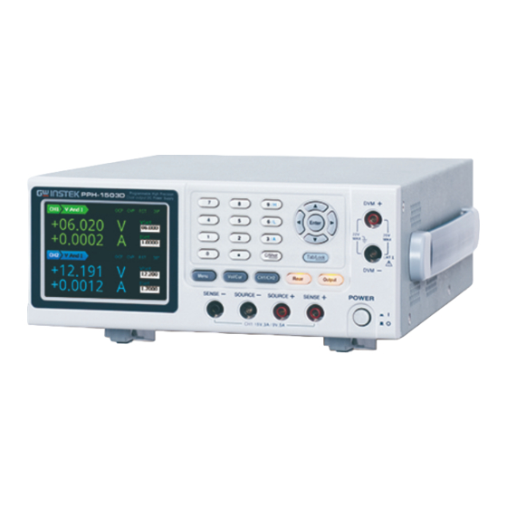
- Page 1 Programmable High Precision Dual Output DC Power Supply PPH-1503D/PPH-1506D/ PPH-1510D User Manual GW INSTEK PART NO. 82PH-1503DED1 Test Equipment Depot - 800.517.8431 - 99 Washington Street Melrose, MA 02176 TestEquipmentDepot.com ISO-9001 CERTIFIED MANUFACTURER...
- Page 2 Copyright Statement This manual contains proprietary information, which is protected by copyright. All rights are reserved. No part of this manual may be photocopied, reproduced or translated to another language without prior written consent of Good Will company. The information in this manual was correct at the time of printing. However, Good Will continues to improve products and reserves the rights to change specification, equipment, and maintenance procedures at any time without notice.
-
Page 3: Table Of Contents
Table of Contents Table of Contents SAFETY INSTRUCTIONS ..........5 OVERVIEW ..............10 Introduction ........... 10 Key Features ........... 12 Operating Principals ........14 Front Panel ............. 16 Rear Panel ............22 Constant Voltage/Constant Current Crossover Characteristics ....... 24 GETTING STARTED ............25 Start Up ............ - Page 4 PPH-1503D/1506D/1510D User Manual SYSTEM SETTINGS ............69 System Information ........69 Utility Settings ..........70 Firmware Upgrading ........72 System Real Time Clock Setting ..... 73 Description of Using Flash Drive ....74 REMOTE CONTROL ............79 Remote Control ..........79 Command Syntax ..........
- Page 6 (Measurement categories) EN 61010-1:2010 specifies the measurement categories and their requirements as follows. The PPH-1503D/1506D /1510D falls under category I. Measurement category IV is for measurement performed at the source of low-voltage installation. Measurement category III is for measurement performed in the building installation.
-
Page 7: Safety Instructions
Temperature: 0°C to 40°C (Pollution Degree) EN 61010-1:2010 specifies pollution degrees and their requirements as follows. The PPH-1503D/1506D/1510D falls under degree 2. Pollution refers to “addition of foreign matter, solid, liquid, or gaseous (ionized gases), that may produce a reduction of dielectric strength or surface resistivity”. - Page 8 PPH-1503D/1506D/1510D User Manual Location: Indoor Storage environment Relative Humidity: < 70% Temperature: -10°C to 70°C ...
- Page 9 SAFETY INSTRUCTIONS Power cord for the United Kingdom When using the power supply in the United Kingdom, make sure the power cord meets the following safety instructions. NOTE: This lead/appliance must only be wired by competent persons WARNING: THIS APPLIANCE MUST BE EARTHED IMPORTANT: The wires in this lead are coloured in accordance with the following code: Green/ Yellow:...
-
Page 10: Overview
Getting Started chapter on page 25 to start up instructions and how to setup the appropriate operation environment. Introduction The PPH-1503D/1506D /1510Dis a high-precision, Overview compact, dual output, multifunction, programmable DC power supply with flexible operating configurations. In addition to the basic... - Page 11 The voltage and current settings and the actual voltage/current are displayed on the LCD. For details, see page 32. The PPH-1503D/1506D /1510D can measure the Pulse Current change in instantaneous current and the current of Measurement Function extremely short pulses.
-
Page 12: Key Features
Remote Control To meet the various needs of customers, the PPH- 1503D/1506D/1510D is designed for USB, GPIB and LAN remote control. For details, see page 79. Additional The PPH-1503D/1506D /1510D has external relay Features control signals for customers. The relay control signals are synced to the pulse current measurement feature. - Page 13 OVERVIEW USB remote control. Interface GPIB remote control. LAN remote control. ...
-
Page 14: Operating Principals
PPH-1503D/1506D/1510D User Manual Operating Principals The PPH-1503D/1506D/1510D mainly consists Overview of the follow components: AC to DC Switching power supply DC to DC Buck converter circuit Precision output control circuit The block diagram below shows a function description of each of the circuits. - Page 15 OVERVIEW The322/Q323, Q622/Q623 dividers reduce the Linear Output heat on a single component. The U330, U327, Circuit (Linear Regulator) U328, U316, U317, U333, U630, U627, U628, U616 and U630 components form a control circuit to achieve accurate output. The independent auxiliary DC power supply is Auxiliary Power achieved with the U101, T101, T201, Q101~Q104 Supply...
- Page 17 OVERVIEW Displays the output current with up to 5 digits of resolution, depending on the current range Ammeter Indicator (CH1:5A or 10A /500mA/5mA/AUTO; PPH-1503D:CH2:1.5A/5mA/AUTO; PPH-1506D/1510D:CH2:3.0A/5mA/AUTO). The current range is selectable between A and mA. CH1: 5A /10A 500mA CH2: 1.5A/3.0A Auto Displays the voltage and current settings.
- Page 21 OVERVIEW Sense terminals for the front panel Voltage CH1 output. Feedback Terminals (SENSE) Digital voltmeter input terminals. Voltmeter Terminals (DVM)
- Page 23 OVERVIEW LAN and USB Host port for LAN & Host remote control. See page 82 for port LAN setting and operation details. See page 74 for details of USB Host setting and operation. A total of 5 ports: 1 positive CH1 rear panel output output terminal, 1 negative...
-
Page 24: Constant Voltage/Constant Current
PPH-1503D/1506D/1510D User Manual Constant Voltage/Constant Current Crossover Characteristics The unit will switch automatically between Background constant voltage and constant current according to changes in the load. When the load current is less than the current CV mode setting, the unit operates in constant voltage mode,... -
Page 25: Getting Started
PPH-1503D/1506D/1510D User Manual ETTING STARTED This chapter describes the start up procedures and the preparation that is necessary before operating the power supply. Start Up Before the power is turned on, Checking the AC confirm that the input power Voltage... -
Page 29: Main Menu Overview
PPH-1503D/1506D/1510D User Manual AIN MENU OVERVIEW This chapter describes each main function and system setting for this device. The following interface will appear when the Menu key is pressed. -
Page 30: Function Description
PPH-1503D/1506D/1510D User Manual Function Description Function Description Function CH1 / CH2 have basic power Source functionality. They can display different current values simultaneously. For details, please refer to page 32, in the section, “BASIC OPERATION”. System Real Time Clock Setting... - Page 31 MAIN MENU OVERVIEW Currently this function is not available. Calibration The real-time clock of the device. The Date/time date/ time are displayed in this area.
-
Page 33: Basic Operation
BASIC OPERATION CH1 and CH2 operate as a basic power supply Description with the ability to simultaneously display V/I settings and readback values. The output from CH1 can be toggled between the front and rear outputs using the Rear key. When the Rear key is lit, it indicates that the rear panel output is activated and that the front panel output is off. - Page 34 PPH-1503D/1506D/1510D User Manual Current limiting mode. There are 4 LimMode settings for the current limiting mode: Limit, Trip, LimitRelay and Trip Relay. The Limit settings will limit the current. When the current reaches the setting value, the current remains constant, as in CC mode.
- Page 35 BASIC OPERATION The relay control settings have 2 RelayControl configurations: Zero/One. The Zero setting means that the output from the Relay control interface OUT port is low and the external relays will energize. The One setting is just the opposite of the Zero setting.
- Page 36 PPH-1503D/1506D/1510D User Manual CH1:0.0000A~3.0000A (0V~15V) Current 0.0000A~5.0000A (0V~9V) 0.0000A~10.0000A (0V~4.5V) (1510D REAR) CH2: 0.0000A~1.5000A (1503D) 0.0000A~3.0000A (1506D/1510D) Press the Vol/Cur key and Parameter Voltage the voltage setting on the Settings (For example LCD is activated. The CH1) corresponding number will turn black on white background.
- Page 37 BASIC OPERATION (b) Step Setting: Press the left and right arrow keys ( ) to fine tune the voltage setting at the digit level (The corresponding number will turn black on white background). Press the up and down arrow keys ) to adjust the selected digit.
- Page 38 PPH-1503D/1506D/1510D User Manual (b) Step Setting: Press the left and right arrow keys ( ) to fine tune the voltage setting at the digit level (The corresponding number will turn black on white background). Press the up and down arrow keys (...
- Page 39 BASIC OPERATION Press the Arrow keys to toggle to AverRead AverRead item. Press the Enter key. Use the numeric keypad to enter desired parameters. Press the Enter key to confirm the setting. The parameter range is from 1 to 10 samples.
- Page 40 PPH-1503D/1506D/1510D User Manual Press the Arrow keys to toggle to Resistance Resistance. Press the Enter key. Use the numeric keys to enter parameters (Range: 0.000 to 1.000 ). Press the Enter key again. Press the Arrow keys to select the other parameters for the setting.
- Page 41 BASIC OPERATION 1. After the parameter settings are complete, press Menu key to return to the display interface. Note Clear 2. The key can't be used to clear numbers that have already been entered. It is necessary to set the number again. 3.
- Page 42 PPH-1503D/1506D/1510D User Manual When the OVP protection has not been activated, it will be greyed-out. Displays the power-on state setting. There are 11 states that can be selected: RST and SAVE0 ~ SAVE9. The state can be set with the PowerOnSetup option in System settings.
-
Page 43: Dvm
BASIC OPERATION The PPH-1503D/1506D /1510D has a separate Description digital voltmeter with a measurement range of 0~+20VDC on CH2. Note: DVM and CH2 have a common ground design. So when using the DVM- terminal, it can’t be shorted with the negative output of CH2. In addition, when using the voltage meter, the power supply must be properly grounded. - Page 44 PPH-1503D/1506D/1510D User Manual I" of CH2. Press Enter key to bring up the Parameter IntRate Settings CH2 parameter setting column. The default setting is IntRate. Press the Enter key. Use numeric keypad to set the parameters (Range: 0.01 to 10.00). Press the Enter key again.
-
Page 45: Pulse Current Measurement
BASIC OPERATION Pulse Current Measurement Changes in the load current allow us to measure Description the pulse current. There are three ways that pulse current can be measured: 1. Measuring the peak current over a single cycle (High Measurement). 2. Measuring the trough current over a single cycle (Low Measurement). - Page 46 PPH-1503D/1506D/1510D User Manual automatic mode, the system will measure the peaks and troughs of the pulse current and will automatically set an appropriate integration time. The average integration time is the time of all the accumulated peaks and troughs. After the setting the...
- Page 47 BASIC OPERATION The setting range for TrigDelay is 0~5 sec.(s)in mode (Pulse current Note digitization) For details, please refer to page 112 Average Reading Count: Reads AverRead back the average number of displayed values. This parameter is only applicable ...
- Page 48 PPH-1503D/1506D/1510D User Manual Integration Time. High Time, Low Time and AverTime options are available for selection. Press the up arrow key to decide to set the integration time automatically or manually set. When manually setting is select, use the numbic keypad to directly select a time setting.
- Page 50 PPH-1503D/1506D/1510D User Manual The measurement settings can be edited during measurement. The H, L, A keys on the keypad can be used to perform fast-switching between measurement modes.
-
Page 51: Long Integration
This can extend the measurement time for long integration to a maximum of 60S. Note: When this feature is used, the current range is set to 5A (CH1 with PPH-1503D/1506D), 10.0A (CH1 with PPH-1510D).1.5A (CH2 with PPH-1503D) , 3.0A (CH2 with PPH-1506D/1510D). - Page 52 PPH-1503D/1506D/1510D User Manual Integration time Parameter IntTime Description The integration time can be set manually or automatically by the operator. For manual settings, the integration time can be set to a maximum of 60 seconds. For a line...
- Page 53 BASIC OPERATION Trigger level. Trig Level When the rising or falling edge trigger is selected for long integration current measurement, a pulse must first be detected. The trigger level refers to minimum pulse level required for a pulse to be detected.
- Page 55 BASIC OPERATION When no pulse current is detected, NO PULSE will be displayed in green (CH1) or in blue (CH2) on the LCD screen. The unit will wait until the next pulse is detected.
-
Page 56: Battery Simulation Function
PPH-1503D/1506D/1510D User Manual Battery simulation function The function can be seen as being equivalent to Function Description power source U in series with resistor R. The equivalent circuit model diagram is shown below: The unit has an internal series resistor that can set the resistance of the circuit to simulate the output voltage of a battery. -
Page 57: Current Sink Function
BASIC OPERATION Current Sink Function When the test circuit is an active circuit, and the Function Description manifested voltage in the test circuit is greater than the output voltage of the power supply, the power supply will automatically disipate current from the external power supply. -
Page 59: External Relay Control
BASIC OPERATION External Relay Control When the Relay control feature is turned on, it is Function Description synced to the current limit of the power supply. The external relay control is divided into two different types, a limit relay and a trip relay. The limit relay is used in conjunction with CC mode. - Page 60 PPH-1503D/1506D/1510D User Manual Schematic Limit Relay: Diagram for Limit setting Relay Control Current Relay Trip Relay: Limit setting Current Output turns off due to Trip Mode User turns output on,and trip condition is Relay corrected.Otherwise,output will trip again.
- Page 61 BASIC OPERATION There are two ways to connect an external relay to External Relay the unit: Connection Using the +5VDC relay output to drive an external relay. Ensure the current doesn’t exceed 150mA. +5VDC Power Supply Relay Relay Control Internal Source +5VDC ±5% Protection Diode...
-
Page 62: Sequence Function
PPH-1503D/1506D/1510D User Manual Sequence Function This function can be used for practical applications Description when different voltage waveforms are required to be output. Users can edit the output waveform according to their needs. The amplitude range of the output waveform is the output voltage range of power supply. - Page 63 BASIC OPERATION Press the Tab key to select the Voltage / V/I/T Current / Time setting area. Setting Press the up and down arrow keys to select the desired Step setting. Press the Enter key to input voltage value. Press the right arrow key to input the current value.
-
Page 64: Save/Recall
PPH-1503D/1506D/1510D User Manual AVE/RECALL Five groups of system settings are available. SAV0, Description SAV1, SAV2, SAV3 & SAV4, respectively. There are a total of 6 different memory settings that can be recalled: Rst, SAV0, SAV1, SAV2, SAV3 and SAV4. Listed below are the settings that are available for... - Page 65 SAVE/RECALL Press the Enter key to go to the Data menu. Use the down arrow keys to expand the six sets of options for the selected channel, RST, SAV0, SAV1, SAV2, SAV3 and SAV4, respectively. Press the down arrow key to select the desired save memory.
- Page 66 PPH-1503D/1506D/1510D User Manual The relationship between SAV0~SAV4 and SAV5~SAV9 is as follows: SAV0 SAV5 SAV1 SAV6 SAV2 SAV7 SAV3 SAV8 SAV4 SAV9 Test Equipment Depot - 800.517.8431 - 99 Washington Street Melrose, MA 02176 TestEquipmentDepot.com...
-
Page 69: System Settings
REMOTE CONTROL YSTEM SETTINGS System Information The System Information menu can be used to view Description the system information or to perform system operations such as set the buzzer function, backlight display brightness or set to the factory conditions. System Version System View the system software version. -
Page 70: Utility Settings
PPH-1503D/1506D/1510D User Manual Utility Settings There are four utility settings: Remote command Description data output format, power-on state setting, buzzer settings and backlight brightness settings. OutputFormat Remote command data output Setting format Information Power-on state setting PowOnSetup Sets when the buzzer is turn on. - Page 71 SYSTEM SETTINGS In the System menu, press Restore to Factory the Tab key to select Reset, Settings and then press the Enter key. A pop-up window will appear as shown on the right. Press the Enter key to compete this step.
-
Page 72: Firmware Upgrading
PPH-1503D/1506D/1510D User Manual Firmware Upgrading When system is failure, request by customer GW When to Upgrade Firmware Instek. When the system fails, firmware can requested by GW Instek customers. Firmware file Supplied by GW Instek Upgrade Requirement Flash drive USB2.0/USB3.0 FAT file... -
Page 73: System Real Time Clock Setting
SYSTEM SETTINGS System Real Time Clock Setting This setting is used to set the display of the real Description time clock. Press the Menu key and press the arrow keys Operation to select icon. Press the Enter key to enter the setting menu. -
Page 74: Description Of Using Flash Drive
PPH-1503D/1506D/1510D User Manual Description of Using Flash Drive It can be use when upgrading the software Description upgrades and importing or exporting files. Please refer to page 72 for upgrading the firmware. Importing and exporting files is mainly used in screenshots and setting the parameter SEQUENCE. - Page 75 SYSTEM SETTINGS After the system identifies the flash Screenshot driver, move the device interface to operation desired interface. Press and hold the C/ Pict key and a window showing the screenshots successful will pop up. Press the Enter key to confirm. The screenshot image will be saved to the PPH- 1503D(PPH-1506D/1510D) / Snapshot folder by default in the flash driver.
- Page 76 Use the arrow keys to select Sequence file. The system will show the Sequence data export confirmation window. Press Enter to confirm. Note: In the flash drive, the default location is in the PPH-1503D(PPH- 1506D/1510D) / User folder.
- Page 77 SYSTEM SETTINGS Use EXCEL to set the Sequence Importing the parameters to the following format and Sequence data save to the flash drive in the computer (* .csv format). A. Insert the flash drive to the USB Host port on the device. B.
- Page 78 PPH-1503D/1506D/1510D User Manual C. Press the up and down arrow keys to select Sequence data. Press the Enter and a message asking to replace the Sequence data appears. Press the Enter key to confirm.
-
Page 79: Remote Control
REMOTE CONTROL EMOTE CONTROL Remote Control The PPH-1503D/1506D can be connected via USB Description using the USB Test & Measurement (TMC) class(Full Speed). Interface Rear panel USB slave port. Installing the Before connecting the unit to the USB Driver port of the PC, Please use “NI Visa”... - Page 80 Perform the following query: Function Check *IDN? The unit will return the manufacturer, model, serial number and software version. GW INSTEK, PPH-1503D, SN: xxxxxxxx, Vx.xx Send a remote command from the PC Disabling Remote Long-press the unlock key on the front panel.
- Page 81 REMOTE CONTROL Set the communication address for the PC to Set the communicate with. communication address A. Press the Menu key to enter the main Steps menu. B. Use the left and right arrow keys to select icon. C. Press Enter to enter the Interface menu.
- Page 82 PPH-1503D/1506D/1510D User Manual Description When using the LAN interface a number of settings must be turned on. IP Mode The IP address can be configured using either DHCP or Manual IP. Using Manu IP A. Press Menu to enter the main menu.
- Page 83 REMOTE CONTROL Parameter Settings: IP Address: IP address range: 1.0.0.0 to 223.255.255.255 (excluding 127.nnn.nnn.nnn). Subnet Mask: Subnet Mask Range: 1.0.0.0 to 255.255.255.255. Gateway: Gateway range: 1.0.0.0 to 223.255.255.255 (excluding 127.nnn.nnn.nnn). DNS Servers: DNS Server range: 1.0.0.0 to 223.255.255.255 (excluding 127.nnn.nnn.nnn). VISA Resource name:...
- Page 84 PPH-1503D/1506D/1510D User Manual PC Operation 1. Enter the IP address into Microsoft Internet Explorer (IE). After entering the IP address you will be shown the Welcome screen which displays the instrument information. The page also provides three links: Welcome Page, Browser Web Control and View &...
- Page 85 REMOTE CONTROL 3. Press the “View & Modify Configuration” icon to enter the Modify Config menu, as shown below. 4. Click “Modify Config” to enter the network configuration setting menu, as shown below. Use the mouse to click on “Save and Restart” to change the remote settings for the PPH- 1503D/1506D/1510D.
-
Page 86: Command Syntax
PPH-1503D/1506D/1510D User Manual Command Syntax The commands that are used with the PPH-1503D/1506D/1510D meet IEEE488.2 and SCPI standards. SCPI Commands Overview SCPI Command Format SCPI is an ASCII based command language designed for test and measurement instruments. SCPI commands uses a hierarchical structure (tree system), and is divided into different subsystems. - Page 87 REMOTE CONTROL Curly Bracket enclose command string parameters, for example: {OFF|ON} 2. Vertical Bars | Vertical bars are used to separate one or more optional parameters. Only one command can be selected. With the following two parameters, {ON|OFF} only ON or OFF can be selected.
- Page 88 PPH-1503D/1506D/1510D User Manual Parameter Types The commands have a number of different parameter categories. How the parameters are set depend on the parameter categories. 1. Boolean Commands parameter that have to states “OFF” and “ON”, for example, DISPlay:FOCUs {ON|OFF}. “ON” will turn on the focus display function, while “OFF”...
- Page 89 REMOTE CONTROL 5. ASCII Strings ASCII string parameters must use a combination of ASCII characters in a string. For example: For the command: MODE <name>, <name> must be an ASCII string. Command Abbreviations The syntax for SCPI commands contains a combination of upper and lower case letters.
-
Page 90: Command List
PPH-1503D/1506D/1510D User Manual Command List Measurement Instructions Page 95 :FETCh[1|2]? Page 95 :FETCh[1|2]:ARRay? Page 96 :READ[1|2]? Page 96 :READ[1|2]:ARRay? Page 96 :MEASure[1|2][:<function>]? Page 97 :MEASure[1|2]:ARRay[:<function>]? Display Functions Page 98 :DISPlay:ENABle <b> Page 98 :DISPlay:ENABle? Page 98 DISPlay:BRIGhtness <NRf> Page 98... - Page 91 REMOTE CONTROL Page 101 :ROUTe:TERMinals? Page 101 :OUTPut[1|2]:RELay <name> Page 101 :OUTPut[1|2]:RELay? Page 101 :OUTPut[1|2]:OVP:STATe <b> Page 102 :OUTPut[1|2]:OVP:STATe? Page 102 :OUTPut[1|2]:OVP <value> Page 102 :OUTPut[1|2]:OVP? Source Commands Page 102 :[SOURce[1|2]]:CURRent[:LIMit][:VALue] <NRf> Page 102 :[SOURce[1|2]]:CURRent[:LIMit][:VALue]? Page 103 :[SOURce[1|2]]:CURRent[:LIMit]:TYPE <name> Page 103 :[SOURce[1|2]]:CURRent[:LIMit]:TYPE? Page 103 :[SOURce[1|2]]:CURRent[:LIMit]:STATe?
- Page 92 PPH-1503D/1506D/1510D User Manual Page 107 :SENSe[1|2]:CURRent[:DC]:RANGe[:UPPer]? Page 108 :SENSe[1|2]:CURRent[:DC]:RANGe:AUTO <b> Page 108 :SENSe[1|2]:CURRent[:DC]:RANGe:AUTO? Page 108 :SENSe[1|2]:PCURrent:AVERage <NRf> Page 108 :SENSe[1|2]:PCURrent:AVERage? Page 108 :SENSe[1|2]:PCURrent:MODE <name> Page 109 :SENSe[1|2]:PCURrent:MODE? Page 109 :SENSe[1|2]:PCURrent:TIME:AUTO Page 109 :SENSe[1|2]:PCURrent:TIME:HIGH <NRf> Page 110 :SENSe[1|2]:PCURrent:TIME:HIGH? Page 110 :SENSe[1|2]:PCURrent:TIME:LOW <NRf>...
- Page 93 REMOTE CONTROL Page 115 :SENSe[1|2]:LINTegration:SEARch <b> Page 115 :SENSe[1|2]:LINTegration:SEARch? Page 115 :SENSe[1|2]:LINTegration:FAST <b> Page 115 :SENSe[1|2]:LINTegration:FAST? Status Commands Page 116 :STATus:PRESet Page 116 :STATus:OPERation[:EVENt]? Page 116 :STATus:OPERation:CONDition? Page 116 :STATus:OPERation:ENABle <NRf> Page 117 :STATus:OPERation:ENABle? Page 117 :STATus:MEASurement[:EVENt]? Page 117 :STATus:MEASurement:ENABle <NRf> Page 118 :STATus:MEASurement:ENABle? Page 118...
- Page 94 PPH-1503D/1506D/1510D User Manual Page 121 :SYSTem:CLEar Page 121 :SYSTem:LFRequnecy? Page 121 :SYSTem:POSetup <name> Page 122 :SYSTem:POSetup? Page 122 :SYSTem:COMMunicate:LAN:DHCP[:STATe] <b> Page 123 :SYSTem:COMMunicate:LAN:DHCP[:STATe]? Page 123 :SYSTem:COMMunicate:LAN:IPADdress <IP address> Page 123 :SYSTem:COMMunicate:LAN:IPADdress? Page 124 :SYSTem:COMMunicate:LAN:SMASk <Mask> Page 124 :SYSTem:COMMunicate:LAN:SMASk? Page 124 :SYSTem:COMMunicate:LAN:GATEway <IP address>...
-
Page 95: Command Details
REMOTE CONTROL Page 128 *RCL <NRf> IEEE488.2 Common Commands Page 135 *SRE <Enable Values> Page 135 *SRE? Page 135 *STB? Page 136 *ESE<Enable Value> Page 136 *ESE? Page 136 *ESR? Page 137 *CLS Page 137 *OPC Page 137 *OPC? Command Details When using commands to select a specific channel, [1] stands for CH1, [2] stands for CH2. -
Page 96: Fetch[1|2]:Array
PPH-1503D/1506D/1510D User Manual :FETCh:ARRay2? Example Returns the last array readback values on CH2. :READ[1|2]? Command Triggers a read operation and returns the read Function values. Maximum: 32ms Response time :READ2? Example Triggers a read operation and returns the read values on CH2. -
Page 97: Measure[1|2]:Array[:
REMOTE CONTROL For pulse current and long integration current measurement, if there is no pulse, test for the timeout time. Maximum: 32ms Response time :MEASure2: CURRent? Example Sets pulse current as the measurement type to CH2 and reads back the pulse current value. :MEASure[1|2]:ARRay[:<function>]? Command Performs a “READ:ARRay?”...] -
Page 98: Display:enable
PPH-1503D/1506D/1510D User Manual Display Commands :DISPlay:ENABle <b> Command Turn the LCD display on or off. Function b 0/OFF: Turns the display off. Description 1/ON: Turns the display on. :DISPlay:ENABle ON Example Turns the LCD display on. :DISPlay:ENABle? Command Queries the state of the display. -
Page 99: Data Format Commands
REMOTE CONTROL Data Format Commands :FORMat[:DATA] <type> Command Sets the data format. Function <type> ASCii:ASCII format. Description SREal:IEEE754 single precision format. DREal:IEEE754 double precision format. :FORMat:DATA SREal Example Sets the format to IEEE754 double precision format. :FORMat[:DATA]? Command Queries the data format. Function :FORMat:DATA? Example... -
Page 100: Output Commands
PPH-1503D/1506D/1510D User Manual Output Commands :OUTPut[1|2][:STATe] <b> Command Turns the output on or off. Function <b> 0/OFF: Turn off the output Description 1/ON: Turn on the output :OUTPut:STATe ON Example Turns on the output. of CH1 :OUTPut[1|2][:STATe]? Command Queries the output state. -
Page 101: Route:terminals
REMOTE CONTROL FRONt: Set the output to the front panel Description REAR: Set the output to the rear panel :ROUTe:TERMinals FRONt Example Sets the output to the front panel :ROUTe:TERMinals? Command Queries the output status of the panel. Function :ROUTe:TERMinals? Example Queries the output status of the panel. -
Page 102: Output[1|2]:Ovp:state
PPH-1503D/1506D/1510D User Manual :OUTPut[1|2]:OVP:STATe? Command Queries the status of the OVP function. Function :OUTPut2:OVP:STATe? Example Returns the status of the OVP function on CH2. :OUTPut[1|2]:OVP <value> Command Sets the OVP level. Function <value> 1.00-15.00 Description :OUTPut2:OVP 10.05 Example Sets the OVP voltage to 10.05V for CH2. -
Page 103: [Source[1|2]]:Current[:Limit]:Type
REMOTE CONTROL :[SOURce[1|2]]:CURRent[:LIMit]:TYPE <name> Command Sets the current limit mode. Function <name> LIMit: General limiting mode Description TRIP: Output shutdown mode LIMRELAY|LIMITRELAY: General limiting mode and external relay output control mode. TRIPRELAY: Output shutdown mode and external relay output control mode. -
Page 104: [Source[1|2]]:Voltage[:Level][:Immediate][:Amplitude]
PPH-1503D/1506D/1510D User Manual :SOURce2:VOLTage 5.321 Example Sets the output voltage to 5.321V for CH2. :[SOURce[1|2]]:VOLTage[:LEVel][:IMMediate] Command [:AMPLitude]? Queries the output voltage setting. Function :SOURce2:VOLTage? Example Queries the output voltage setting on CH2. :[SOURce]:RESistance[:LEVel][:IMMediate][:AMP Command Litude] < NRf > Set the resistance value Function 000-1.000... -
Page 105: Sense[1|2]:Nplcycles
REMOTE CONTROL name “VOLTage”: Voltage measurement. Description “CURRent”: Current measurement. “PCURrent”: Pulse current measurement. “LINTegration”: Long integration measurement. “DVMeter”: DVM input measurement. :SENSe2:FUNCtion “VOLTage” Example Selects “Voltage” as the measurement type for CH2. :SENSe[1|2]:FUNCtion? Command Queries the type of measurement function. Function Maximum: 16ms Response time... -
Page 106: Sense[1|2]:Average
PPH-1503D/1506D/1510D User Manual :SENSe[1|2]:AVERage <NRf> Command Sets the averaging number for the voltage, current Function and DVM measurements. <NRf> 1-10 Description :SENSe2:AVERage 3 Example Sets the averaging number to 3 for CH2. Test Equipment Depot - 800.517.8431 - 99 Washington Street Melrose, MA 02176... -
Page 107: Sense[1|2]:Average
REMOTE CONTROL :SENSe[1|2]:AVERage? Command Queries the averaging number for the voltage, Function current and DVM measurements. :SENSe2:AVERage? Example Queries the averaging number for the voltage, current and DVM measurements on CH2. :SENSe[1]:CURRent[:DC]:RANGe[:UPPer] <n> Command Sets the current measurement range. Function <n>... -
Page 108: Sense[1|2]:Current[:Dc]:Range:auto
PPH-1503D/1506D/1510D User Manual :SENSe[1|2]:CURRent[:DC]:RANGe:AUTO <b> Command Turns the automatic range function on or off. Function <b> 0/OFF: Turn off. Description 1/ON: Turn on. :SENSe2:CURRent:RANGe:AUTO ON Example Turns on the automatic range function on CH2. :SENSe[1|2]:CURRent[:DC]:RANGe:AUTO? Command Queries the state of the automatic range function. -
Page 109: Sense[1|2]:Pcurrent:time:auto
REMOTE CONTROL Name HIGH: High pulse mode (trigger on the Description rising edge). LOW: Low pulse mode (trigger on the falling edge) AVERage: Average pulse measurement. :SENSe2:PCURrent:MODE HIGH Example Sets the pulse current measurement mode to HIGH mode for CH2. :SENSe[1|2]:PCURrent:MODE? Command Queries the pulse current measurement mode. -
Page 110: Sense[1|2]:Pcurrent:time:high
PPH-1503D/1506D/1510D User Manual IntTime setting is automatically changed to 33.3 us in Note Pulse current digitization mode. :SENSe[1|2]:PCURrent:TIME:HIGH? Command Queries integration time for high pulse Function measurement. :SENSe2:PCURrent:TIME:HIGH? Example Queries the integration time for high pulses on CH2. IntTime setting is automatically changed to 33.3 us in Note Pulse current digitization mode. -
Page 111: Sense[1|2]:Pcurrent:time:average
REMOTE CONTROL :SENSe[1|2]:PCURrent:TIME:AVERage <NRf> Command Sets the integration time for the average pulse Function measurement. 33-833333, step resolution of 33.3 Description :SENSe2:PCURrent:TIME:AVERage 0.000233 Example Sets the integration time for average pulse measurement to 233 microseconds for CH2. IntTime setting is automatically changed to 33.3 us in Note Pulse current digitization mode. -
Page 112: Sense[1|2]:Pcurrent:synchronize[:State]
PPH-1503D/1506D/1510D User Manual :SENSe[1|2]:PCURrent:SYNChronize[:STATe]? Command Queries the pulse current measurement triggering Function option. :SENSe2:PCURrent:SYNChronize? Example Queries the pulse current trigger option on CH2. :SENSe[1|2]:PCURrent:SYNChronize:DELay Command <NRf> Sets the trigger delay time. Function 0~0.1 or 0~5 ( Pulse current digitization ) <NRf>... -
Page 113: Sense[1|2]:Lintegration:time
REMOTE CONTROL :SENSe2:PCURrent:SYNChronize:TLEVel? Example Queries the trigger level on CH2. :SENSe[1|2]:LINTegration:TIME <NRf> Command Sets the long integration time. Function (power line frequency: X=0.84~60.0000 <NRf> Description for 50Hz. Resolution is 20mS; X=0.850~60.000 for 60Hz. Resolution is 16.7mS) :SENSe2:LINTegration:TIME 1.2 Example Sets the long integration time to 1.2S for CH2. :SENSe[1|2]:LINTegration:TIME?... -
Page 114: Sense[1|2]:Lintegration:tlevel
PPH-1503D/1506D/1510D User Manual :SENSe[1|2]:LINTegration:TLEVel? Command Queries the long integration trigger level setting. Function :SENSe2:LINTegration:TLEVel? Example Queries the long integration trigger level on CH2. :SENSe[1|2]:LINTegration:TEDGe <name> Command Sets the long integration triggering edge. Function <name> RISING: Rising triggering edge. Description FALLING: Falling triggering edge. -
Page 115: Sense[1|2]:Lintegration:search
REMOTE CONTROL :SENSe2:LINTegration:TimeOUT? Example Queries the timeout time on CH2. :SENSe[1|2]:LINTegration:SEARch <b> Command Turns the long integration pulse measurement Function search function on or off. <b> 0/OFF: Disable Description 1/ON: Enable :SENSe2:LINTegration:SEARch ON Example Turns on the search function of CH2. :SENSe[1|2]:LINTegration:SEARch? Command Queries the long integration search function state. -
Page 116: Status Commands
PPH-1503D/1506D/1510D User Manual :SENSe2:LINTegration:FAST? Example Query the state of the long integration fast measurement mode on CH2. Status Commands :STATus:PRESet Command Clears the operation event enable registers, the Function measurement event enable registers and the questionable event register, The unit will then return to the default settings status. -
Page 117: Status:operation:enable
REMOTE CONTROL :STATus:OPERation:ENABle 64 Example Enable the power supply shutdown bit. :STATus:OPERation:ENABle? Command Read the operation enable status register. Function :STATus:OPERation:ENABle? Example Read the contents of the operation enable status register. :STATus:MEASurement[:EVENt]? Command Reads the measurement event status register. Function :STATus:MEASurement? Example Reads the contents of the measurement event... -
Page 118: Status:measurement:enable
PPH-1503D/1506D/1510D User Manual :STATus:MEASurement:ENABle? Command Read the measurement enable status register. Function :STATus:MEASurement:ENABle? Example Read the contents of the measurement enable status register. :STATus:MEASurement:CONDition? Command Read the measurement condition status register. Function :STATus:MEASurement:CONDition? Example Read the contents of the measurement condition status register. -
Page 119: Status:questionable:enable
REMOTE CONTROL :STATus:QUEStionable:ENABle 256 Example Sets the CAL bit. :STATus:QUEStionable:ENABle? Command Read the questionable enable status register. Function :STATus:QUEStionable:ENABle? Example Read the contents of the questionable enable status register. :STATus:QUEue[:NEXT]? Command Read the next message in the error queue. Function :STATus:QUEue? Example Read the next error message. -
Page 120: Status:queue:enable
PPH-1503D/1506D/1510D User Manual :STATus:QUEue:ENABle? Command Read the error and status messages that have been Function enabled. :STATus:QUEue:ENABle? Example Returns the contents of the enabled error and status messages. :STATus:QUEue:DISable <list> Command Specifies which messages will not be placed in the Function error queue. -
Page 121: System Commands
REMOTE CONTROL System Commands :SYSTem:VERSion? Command Query the SCPI version. Function :SYSTem:VERSion? Example Query the SCPI version. :SYSTem:ERRor? Command Read and clear the last error and from the error Function queue. :SYSTem:ERRor? Example Read and clear the last error and from the error queue. -
Page 122: System:posetup
PPH-1503D/1506D/1510D User Manual SAV2: User settings stored in memory location 2 (output off). SAV3: User settings stored in memory location 3 (output off). SAV4: User settings stored in memory location 4 (output off). SAV5: User settings stored in memory location 5. -
Page 123: System:communicate:lan:dhcp[:State]
REMOTE CONTROL Note: The :SYSTem:COMMunicate:LAN:APPLy command must be executed before the DHCP settings can take effect. :SYSTem:COMMunicate:LAN:DHCP ON Example Enable DHCP. :SYSTem:COMMunicate:LAN:DHCP[:STATe]? Command Query the DHCP status. Function :SYSTem:COMMunicate:LAN:DHCP? Example Query the DHCP state. :SYSTem:COMMunicate:LAN:IPADdress Command <IPaddress> Sets the IP address. Function <IP ASCII string, within the range of 1.0.0.0... -
Page 124: System:communicate:lan:smask
PPH-1503D/1506D/1510D User Manual :SYSTem:COMMunicate:LAN:SMASk <mask> Command Sets the subnet mask. Function ASCII string, within the range of 1.0.0.0 <mask> Description to 255.255.255.255. The SYSTem:COMMunicate:LAN:APPLy command needs to be executed before the subnet mask setting can take effect. :SYSTem:COMM:LAN:SMAS 255.255.255.0 Example Sets the subnet mask to 255.255.255.0. -
Page 125: System:communicate:lan:dns
REMOTE CONTROL :SYSTem:COMMunicate:LAN:GATEway? Example Queries the gateway IP. :SYSTem:COMMunicate:LAN:DNS <IPaddress> Command Sets the DNS IP address. Function ASCII string, within the range of <IP address> Description 1.0.0.0 to 223.255.255.255 (excluding 127.nnn.nnn.nnn). The SYSTem:COMMunicate:LAN:APPLy command needs to be executed before the DNS IP address setting can take effect. -
Page 126: System:communicate:lan:apply
PPH-1503D/1506D/1510D User Manual :SYSTem:COMMunicate:LAN:MANualip? Example Queries the status of the manual IP addressing. :SYSTem:COMMunicate:LAN:APPLy Command When this command is executed, all the LAN Function settings are applied. :SYSTem:COMMunicate:LAN:APPLy Example Applies all the LAN settings. :SYSTem:REMote Command Sets the unit to remote control. -
Page 127: System:local
*IDN? Example Returns: GW,PPH-1503D,XXXXXXXX,V0.62 GW: Manufacturer, PPH-1503D: Model name, XXXXXXXX: Serial number, V0.62: version number. Returns the PPH identification. *RST Command Resets the unit to RST default conditions. -
Page 128: Wai
PPH-1503D/1506D/1510D User Manual *TST? Example Return 0 if there are no errors, returns 2 if there is an error. *WAI Command Waits for all pending operations to be completed Function before allowing other operations to be executed. *WAI Example *TRG Command Sends a bus trigger. - Page 129 REMOTE CONTROL <NRf> 0: Recall SAV0 from memory. Description 1: Recall SAV1 from memory. 2: Recall SAV2 from memory. 3: Recall SAV3 from memory. 4: Recall SAV4 from memory. *RCL 2 Example Recalls the user save settings from SAV2...
-
Page 130: Scpi Status Registers Scpi
PPH-1503D/1506D/1510D User Manual SCPI Status Registers SCPI The SCPI instrument configuration is controlled by the status registers. The Status system records various instrument conditions into three main register groups: The status byte register, the standard event register group and the questionable data register group. - Page 131 REMOTE CONTROL *Note: URQ indicates that the "Lock" key on the panel has been used. (Entering lock from unlock or Entering unlock from lock).
- Page 132 PPH-1503D/1506D/1510D User Manual Event Registers The operation, measurement and questionable status register groups all have event registers. The event registers are read only registers that reflect the status of the unit. Individual bits in the event registers are latched (set) when a corresponding event occurs and will remain latched even if the corresponding event changes, as long as the event bit is still set.
- Page 133 REMOTE CONTROL Bit Definition for the Status Byte Register Bit number Decimal Definition value Not used, returns “0” 0 Not used Not used, returns “0” 1 Not used Indicates that one or more errors 2 Error Queue are stored in the error queue. One or more bits are set in the 3 Questionable questionable data register (for...
- Page 134 PPH-1503D/1506D/1510D User Manual completed. After executing the *OPC command, the OPC bit will be set to 1. If a command or query is placed in the output buffer immediately before the *OPC command is sent, the Operation Complete Bit can be used to determine when the information can be used.
-
Page 135: Sre
REMOTE CONTROL 6 Not used Not used, return 0. 7 Power On This bit is set if the power supply has been reset from the last time you read the event register. The following will clear the standard event register: •The *CLS command is executed. -
Page 136: Ese
PPH-1503D/1506D/1510D User Manual Function Query the status byte register. This is the same as performing a serial poll, however the master summary bit (MSS, bit 6) will not be cleared by the *STB command. The return value range is from 0 to 255. -
Page 137: Cls
REMOTE CONTROL Other Status Register Commands Command *CLS Function Clears the status byte summary registers and the all event registers. Example *CLS Clears all the event registers. 涵盖 Standard event registers, Operation event registers, Measurement event registers, Questionable event registers. Command *OPC After all the pending operations are complete, sets... -
Page 138: Errors
PPH-1503D/1506D/1510D User Manual Errors Error Message •Errors are stored in a first in-first out (FIFO) order. The first error message that is returned is the first error message that was stored. When an error is read it is also cleared from the queue. - Page 139 REMOTE CONTROL -225 Data corrupt or stale -224 Out of memory -223 Illegal parameter value -222 Too much data -221 Parameter data out of range -220 Settings conflict -200 Parameter error -178 Execution error -171 Expression data not allowed -170 Invalid expression -161 Expression error...
- Page 140 PPH-1503D/1506D/1510D User Manual -110 Command header error -109 Missing parameter -108 Parameter not allowed -105 GET not allowed -104 Data type error -103 Invalid separator -102 Syntax error -101 Invalid character -100 Command error +000 No error +101 Operation complete +301 Reading overflow...
- Page 141 REMOTE CONTROL +610 Questionable calibration +900 Internal system error...
-
Page 143: Appendix
APPENDIX Battery Replacement Remove the handle. Step Remove the six screws on both sides and the four screws on the rear. Open the cover. Find the location indicated by the arrow in the figure shown below and then replace the battery with a new one. -
Page 147: Declaration Of Conformity
GOOD WILL INSTRUMENT CO., LTD. Model Number: PPH-1503D(1506D/J.510D declare, that the below mentioned product Type of Product: G!!!lnSTEK APPENDIX Declaration of Conformity Programmable High Precision Power Supply satisfies all the technical relations application to the product within the scope of council: Directive: 2014/30/EU;...
Need help?
Do you have a question about the PPH-1503D and is the answer not in the manual?
Questions and answers