PSM-SERIES PROGRAMMABLE POWER SUPPLY PSM-SERIES PROGRAMMABLE POWER SUPPLY USER MANUAL USER MANUAL 4-1. F ..................8 RONT ANEL This manual contains proprietary information, which is protected by 4-2. R ................10 ANEL BRIEF copyrights. All rights are reserved. No part of this manual may be 4-3.
Page 3
PSM-SERIES PROGRAMMABLE POWER SUPPLY PSM-SERIES PROGRAMMABLE POWER SUPPLY USER MANUAL USER MANUAL SAFETY TERMS AND SYMBOLS 6. MAINTENANCE.................43 These terms may appear in this manual or on the product: 6-1. F ...............43 EPLACEMENT 6-2. L ............43 OLTAGE ONVERSION WARNING. Warning statements identify condition or 6-3.
Page 4
PSM-SERIES PROGRAMMABLE POWER SUPPLY PSM-SERIES PROGRAMMABLE POWER SUPPLY USER MANUAL USER MANUAL This cable/appliance should be protected by a suitably rated and FOR UNITED KINGDOM ONLY approved HBC mains fuse: refer to the rating information on the equipment and/or user instructions for details. As a guide, cable of 0.75mm should be protected by a 3A or 5A fuse.
PSM-SERIES PROGRAMMABLE POWER SUPPLY PSM-SERIES PROGRAMMABLE POWER SUPPLY USER MANUAL USER MANUAL 1. PRODUCT INTRODUCTION Declaration of Conformity 1-1. Description GOOD WILL INSTRUMENT CO., LTD. PSM-series 
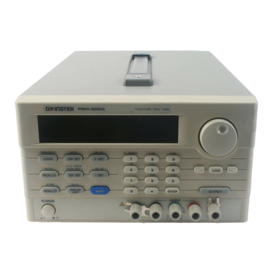
Programmable Power Supply is controlled by Micro Processor No. 7-1, Jhongsing Rd., Tucheng City, Taipei County 236, Taiwan GOOD WILL INSTRUMENT (SUZHOU) CO., LTD.
USER MANUAL USER MANUAL 2. TECHNICAL SPECIFICATIONS 1-2. Feature An overall digitalization of programmable interface with high resolution Specification PSM-2010 PSM-3004 PSM-6003 Low Range 0~ +8V / 0~20A 0~ +15V / 0~ 7A 0~ +30V / 0~6A and accuracy. DC Output...
Page 7
PSM-SERIES PROGRAMMABLE POWER SUPPLY PSM-SERIES PROGRAMMABLE POWER SUPPLY USER MANUAL USER MANUAL Specification PSM-2010 PSM-3004 PSM-6003 Specification PSM-2010 PSM-3004 PSM-6003 Voltage 0.02% + 1mV Accuracy Current 0.1% + 1mA Programming Voltage 0.05% + 10mV Memory Store/Recall points 0~99 (@23¢ J ±5¢ J ) Temperature Coefficient per ¢...
When line voltages are changed, replace the required fuses shown as below: Line Line Model Range Fuse Range Fuse voltage voltage T 7A T3.15A PSM-2010 250V 250V 90-110V T3.15A 220V 198-242V T 1.6A 100V PSM-3004 108-132V 250V 230V...
PSM-SERIES PROGRAMMABLE POWER SUPPLY PSM-SERIES PROGRAMMABLE POWER SUPPLY USER MANUAL USER MANUAL Set the voltage and current output time in the 4. PANEL INTRODUCTION 15. DELAY automatic operation mode. Proceed setting step by step. During setting 4-1. Front Panel AUTO RANGE proceeding, press this key can display the Connect the AC power, then press ON/OFF (AUTO INFO)
PSM-SERIES PROGRAMMABLE POWER SUPPLY PSM-SERIES PROGRAMMABLE POWER SUPPLY USER MANUAL USER MANUAL Adjust the intensity of VFD. After pressing 4-3. Display brief [SHIFT], can press [FL DIMMER] continually 27. FL DIMMER until the required brightness is reached. Then Set the power supply to the address of Listen or 1.
Page 11
PSM-SERIES PROGRAMMABLE POWER SUPPLY PSM-SERIES PROGRAMMABLE POWER SUPPLY USER MANUAL USER MANUAL When the power supply is set to operation mode, the symbol of “¡ ¯ ” will be lighted up. When the Output is on, the symbol of “¡ ¯ ” 9.
PSM-SERIES PROGRAMMABLE POWER SUPPLY PSM-SERIES PROGRAMMABLE POWER SUPPLY USER MANUAL USER MANUAL 5. OPERATION INSTRUCTION 5-1. Basic Operation The applied Voltage/Current Unit for this series instruments is Volt and Amp. The Instrument requires 30 minutes warm-up with no load before operation or calibration to achieve rated accuracy.
PSM-SERIES PROGRAMMABLE POWER SUPPLY PSM-SERIES PROGRAMMABLE POWER SUPPLY USER MANUAL USER MANUAL display measurement value (the symbol of “¡ ¯ ”is blinking). Besides, When the output is set to OFF, the OUTPUT OFF message will be displayed on the front panel, the setting still can be modified. At the same when the operation is set to “DISPLAY LIMIT”...
Page 14
PSM-SERIES PROGRAMMABLE POWER SUPPLY PSM-SERIES PROGRAMMABLE POWER SUPPLY USER MANUAL USER MANUAL I SET : Output current setting When the current load runs through output terminal, if the current The minimum resolution of output current is at 1mA(output¡ Ù 10A at exceeds the setting value, the operation of the instrument will be set to 10mA).
Page 15
PSM-6003 ¡ G 60V,3.3A/30V,6A Current Protection Delay setting (The minimum Delay time is at 0 For example: Set output range of PSM-2010 to 20V, 10A second, the maximum is at 10second, and the scale base is 0.1 second). Press [SHIFT][20V,10A], the output range will be changed to 20V,10A.
Page 16
PSM-SERIES PROGRAMMABLE POWER SUPPLY PSM-SERIES PROGRAMMABLE POWER SUPPLY USER MANUAL USER MANUAL DELAY : The Auto mode setting for the voltage/current Delay time RECALL : Recall the setting data from the memory bank Setting method: Press [SHIFT] [DELAY] to appear the “MIN.” setting item Remark: selection, then input setting value and press [ENTER] to “SEC.”...
Page 17
PSM-SERIES PROGRAMMABLE POWER SUPPLY PSM-SERIES PROGRAMMABLE POWER SUPPLY USER MANUAL USER MANUAL AUTO RANGE STORE : Save the setting data to one of the memory groups STORE setting method: Press the function of [STORE], use knob or AUTO RANGE Setting method: Press [SHIFT][AUTO RANGE] , use number key to input the memory address to save the data.
Page 18
PSM-SERIES PROGRAMMABLE POWER SUPPLY PSM-SERIES PROGRAMMABLE POWER SUPPLY USER MANUAL USER MANUAL GPIB or RS-232 and press [ENTER] to confirm the setting. If want to set For example: Select RS-232 communication interface and set the BAUD to GPIB, use knob to select input address, then press [ENTER] to rate to 9600.
Page 19
PSM-SERIES PROGRAMMABLE POWER SUPPLY PSM-SERIES PROGRAMMABLE POWER SUPPLY USER MANUAL USER MANUAL OUTPUT : Turn on/off the output V STEP : The step setting of voltage. When the output is set to OFF, the OUTPUT OFF message will be displayed on the front panel, and the CC and CV indicators are off, but the rest of indicators keep at the original setting.
PSM-SERIES PROGRAMMABLE POWER SUPPLY PSM-SERIES PROGRAMMABLE POWER SUPPLY USER MANUAL USER MANUAL For example: Set the “I STEP” to 1.000A. 5-3. Operation Method Press [SHIFT] [I STEP], then input [1][.][0][0][0][ENTER] to complete The applied Voltage/Current Unit for this series instruments is Volt and and store the current step setting.
Page 21
PSM-SERIES PROGRAMMABLE POWER SUPPLY PSM-SERIES PROGRAMMABLE POWER SUPPLY USER MANUAL USER MANUAL 5) Start the output: 4) Set the desired output current value: Press [OUTPUT] to enable output, now, the meter displays the Press [I SET], the panel operation is set to current value input actual output measurement value.
Page 22
PSM-SERIES PROGRAMMABLE POWER SUPPLY PSM-SERIES PROGRAMMABLE POWER SUPPLY USER MANUAL USER MANUAL Firstly, remove the external test unit, such as battery, from the 2) Store the present setting status to the memory bank: instrument, adjust the voltage down or raise up the OVP level, Press [SHIFT][STORE], set the panel operation to Storing setting then clear the OVP.
Page 23
PSM-SERIES PROGRAMMABLE POWER SUPPLY PSM-SERIES PROGRAMMABLE POWER SUPPLY USER MANUAL USER MANUAL 2) The setting and store of very group of data: The flow chart of the Auto Running Operation A group setting includes the Output range, Output voltage value, Output current value, Over Voltage protection level, Over Current protection level, Over Voltage status (ON/OFF), and Delay time.
Page 24
PSM-SERIES PROGRAMMABLE POWER SUPPLY PSM-SERIES PROGRAMMABLE POWER SUPPLY USER MANUAL USER MANUAL The Remote voltage sensing of the front/rear panel terminals: The remote voltage sensing circuit is to compensate the voltage drop occurred on the power supply and load terminal during load adding. When proceed the remote voltage sensing, the probe connected between the output of power supply and the sensing terminal must be removed.
PSM-SERIES PROGRAMMABLE POWER SUPPLY USER MANUAL USER MANUAL description. 5-4. The maximum value of the output setting RS232 cable configuration: PSM-2010 PSM-3004 PSM-6003 Model Figure 5-4 RS-232 Cable Configuration Output Range Please enter to our web site for updated information: 8V,20A 20V,10A 15V,7A 30V,4A 30V,6A 60V,3.3A...
PSM-SERIES PROGRAMMABLE POWER SUPPLY USER MANUAL USER MANUAL 6. MAINTENANCE 5-5. Test Lead Table 1: Model PSM-2010 PSM-3004 PSM-6003 GTL-104 or GTL-204 Test Lead (The maximum current: 10A) The following instructions are executed by qualified personnel only. To avoid electrical shock, do no perform any servicing other than the operating Note: The attached test lead to the PSM-SERIES is only used for the front instructions unless you are qualified to do so.
PSM-SERIES PROGRAMMABLE POWER SUPPLY PSM-SERIES PROGRAMMABLE POWER SUPPLY USER MANUAL USER MANUAL (1) Make sure the power cord is unplugged. The resistor must have sufficient Watt value that can meet the (2) Change the AC selects switch to the desired line voltage position. calibration need to control the change amount less than 15mA A change in line voltage may also require a corresponding change of when a 20.00A current run over it for a long period.
Next, proceed the calibration procedure of MI calibrated point, input DMM measurement value, then press [ENTER]. with different models: PSM-2010= 2010, PSM-3004 = 3004, PSM-6003 = 6003) by using the number key, press [ENTER] key Note: The DMM selected for the measurement must have the resolution of...
Page 29
PSM-SERIES PROGRAMMABLE POWER SUPPLY PSM-SERIES PROGRAMMABLE POWER SUPPLY USER MANUAL USER MANUAL [Step 5.1] Set to [O.V.P.] by using the knob and press [ENTER] getting into Over Voltage Protection auto-calibration procedure. Now, the output is in CV Firstly, proceed the calibration procedure of LO calibrated point, input mode (output terminal open).
PSM-SERIES PROGRAMMABLE POWER SUPPLY PSM-SERIES PROGRAMMABLE POWER SUPPLY USER MANUAL USER MANUAL Now, switch to SAVE by using the knob and press [ENTER] to leave the [Step 7] mode with storing. Also can press [SHIFT][ .] to leave the mode without Set to [SAVE] and press [ENTER] to complete the calibration procedure storing.
PSM-SERIES PROGRAMMABLE POWER SUPPLY PSM-SERIES PROGRAMMABLE POWER SUPPLY USER MANUAL USER MANUAL 7. THE SYSTEM DIAGRAM AND DESCRIPTION 7-2. The Configuration of Block System 7-1. Block Diagram The whole Block system consists of two Circuit Blocks, Digital Control The graph above is the system diagram of PSM-SERIES, which consists of circuit (connected to the ground) and power output circuit (isolated from Micro Processor Unit (MPU), Digital to Analog Converter (DAC), Analog the ground):...
Need help?
Do you have a question about the PSM-2010 and is the answer not in the manual?
Questions and answers