
Subscribe to Our Youtube Channel
Related Manuals for GW Instek PPH-1503


Summary of Contents for GW Instek PPH-1503
- Page 1 Programmable High Precision DC Power Supply PPH-1503 User Manual GW INSTEK PART NO. 82PH-15030EE1 ISO-9001 CERTIFIED MANUFACTURER 北京海洋兴业科技股份有限公司(证券代码:839145) 电话:010-62176775 网址:www.hyxyyq.com...
- Page 2 Copyright Statement This manual contains proprietary information, which is protected by copyright. All rights are reserved. No part of this manual may be photocopied, reproduced or translated to another language without prior written consent of Good Will company. The information in this manual was correct at the time of printing. However, Good Will continues to improve products and reserves the rights to change specification, equipment, and maintenance procedures at any time without notice.
-
Page 3: Table Of Contents
TABLE OF CONTENTS Table of Contents SAFETY INSTRUCTIONS ............ 5 OVERVIEW ..............11 Introduction ............ 11 Key Features ........... 13 Operating Theory ..........15 Front Panel ............. 17 Rear Panel............23 Constant Voltage/Constant Current Crossover Characteristics ..........25 GETTING STARTED ............27 Start Up ............ - Page 4 PPH-1503 User Manual Restore Factory Default Settings ...... 69 SYSTEM SETTINGS ............71 System Information ......... 71 Utilty Settings ..........72 Updating Firmware.......... 74 REMOTE CONTROL ............77 Remote Control ..........77 Command Syntax..........87 Command List ..........91 Command Details ..........97 SCPI Status Registers SCPI ......
-
Page 5: Safety Instructions
SAFETY INSTRUCTIONS AFETY INSTRUCTIONS This chapter contains important safety instructions that you must follow during operation and storage. Read the following before any operation to insure your safety and to keep the instrument in the best possible condition. Safety Symbols These symbols may appear in the manual or on the instrument. - Page 6 PPH-1503 User Manual Do not dispose electronic equipment as unsorted municipal waste. Please use a separate collection facility or contact the supplier from which this instrument was purchased. 北京海洋兴业科技股份有限公司(证券代码:839145) 电话:010-62176775 网址:www.hyxyyq.com...
- Page 7 SAFETY INSTRUCTIONS Safety Guidelines Do not place any heavy object on the unit. • General Guideline Avoid severe impact or rough handling that • CAUTION leads to damaging the unit. Do not discharge static electricity to the unit. • Do not block the cooling fan opening. •...
- Page 8 PPH-1503 User Manual Fuse type: T2.0A/250V • Fuse To prevent fire, replace the fuse only with the • WARNING specified type and rating. Disconnect the power cord before replacing the • fuse. Make sure the cause of fuse blowout is fixed •...
- Page 9 SAFETY INSTRUCTIONS (Pollution Degree) EN 61010-1:2001 specifies pollution degrees and their requirements as follows. The PPH-1503 falls under degree 2. Pollution refers to “addition of foreign matter, solid, liquid, or gaseous (ionized gases), that may produce a reduction of dielectric strength or surface resistivity”.
- Page 10 PPH-1503 User Manual Power cord for the United Kingdom When using the power supply in the United Kingdom, make sure the power cord meets the following safety instructions. NOTE: This lead/appliance must only be wired by competent persons WARNING: THIS APPLIANCE MUST BE EARTHED...
-
Page 11: Overview
OVERVIEW VERVIEW This chapter contains a brief introduction to PPH-1503, the main features, as well as an overview of the front and rear panel. Use the Getting Started chapter on page to for start up instructions and how to setup the appropriate operation environment. - Page 12 For details, see page 56. Digital Volt The PPH-1503 has a DVM function that can Meter measure DC voltages in the range of 0~20VDC. For details, see page 42.
-
Page 13: Key Features
OVERVIEW Additional The PPH-1503 has external relay control signals for Features customers. The relay control signals are synced to the pulse current measurement feature. For details, see page 58. Key Features Low noise: Thermostatically controled fan. • Features Compact, lightweight. - Page 14 PPH-1503 User Manual USB remote control. • Interface GPIB remote control. • LAN remote control. • 北京海洋兴业科技股份有限公司(证券代码:839145) 电话:010-62176775 网址:www.hyxyyq.com...
-
Page 15: Operating Theory
OVERVIEW Operating Theory The PPH-1503 mainly consists of the follow Overview components: AC to DC Switching power supply • DC to DC Buck converter circuit • Precision output control circuit • The block diagram below shows a function description of each of the circuits. The following page will show detailed decriptions of each component. - Page 16 PPH-1503 User Manual The Q306, Q307 dividers reduce the heat on a Linear Output single component. The U303, U301, U403, U401 Circuit (Linear and U402 components form a control circuit to Regulator) achieve accurate output. The independent auxillary DC power supply is...
-
Page 17: Front Panel
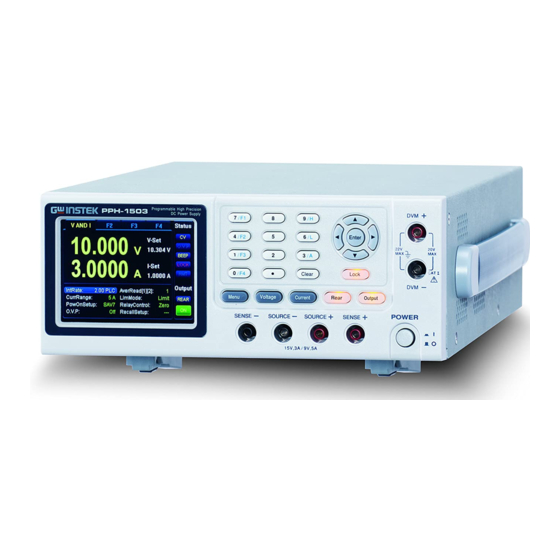
OVERVIEW Front Panel Numberpad and secondary function keys DVM inputs LCD display Arrow keys P P H -1 5 0 3 Front panel output Power button terminals Function keys Display Displays the output voltage with up to 5 digits of Voltmeter resolution. - Page 18 PPH-1503 User Manual 5.0000 5.0000 Displays the voltage and current settings. Setting Display 09.200 V I-Set 5.0000 A Displays the parameter settings. For details on setting Parameter parameters, see page 20. The following figure shows the Settings F1 parameter settings (V AND I), for example.
- Page 19 OVERVIEW LOCK LOCK Locked: Unlocked: Remote connectivity GPIB Local mode: Remote: Output Switching the Output Source FRONT REAR Front: Rear: Output State Off: Displays the unit functions. There four functions: Function Display F1: Basic power supply function (V AND I); F2: Digital Voltmeter function (DVM);...
- Page 20 PPH-1503 User Manual Press the Current key to set the Current current settings. See page 35 for Setting key operation details. Front and rear output toggle Front and switch. The key will be lit when Rear output the output is set to the rear toggle key outputs.
- Page 21 OVERVIEW a. The numberpad is used to enter Numberpad various parameters and values. The Clear key can be used to clear set parameters. F1/F2/F3/F4 function short cuts. Press any of the function short cuts when in the main menu to enter the corresponding function interface.
- Page 22 PPH-1503 User Manual Turns the power on or off. Power Button Off: Terminals Output source terminals. Output Terminals (SOURCE) Sense terminals. Voltage Feedback Terminals (SENSE) Digital voltmeter input Voltmeter terminals. Terminals (DVM) 北京海洋兴业科技股份有限公司(证券代码:839145) 电话:010-62176775 网址:www.hyxyyq.com...
-
Page 23: Rear Panel
OVERVIEW Rear Panel AC power socket Rear panel outputs and Relay control and fuse DVM inputs port Lan port GPIB port Heat sink fan USB port Terminals The AC input: AC input 90~264VAC, 50Hz/60Hz socket and Fuse: 2A slow-blow type. See page line fuse for details. - Page 24 PPH-1503 User Manual LAN port for remote control. See LAN port page for details. A total of 8 ports: 2 positive output Output terminals, 2 negative output interface terminals, a Sense+ terminal, a Sense- terminal, a DVM- input terminal and a DVM+ input terminal.
-
Page 25: Constant Voltage/Constant Current Crossover Characteristics
OVERVIEW Constant Voltage/Constant Current Crossover Characteristics The unit will switch automatically between Background constant voltage and constant current according to changes in the load. When the load current is less than the current CV mode setting, the unit operates in constant voltage mode, changing the current level according to the load but maintaining the set voltage level until the current reaches the set current level. - Page 26 PPH-1503 User Manual Diagram Vout Vmax Constant Voltage Constant Current Iout Imax 北京海洋兴业科技股份有限公司(证券代码:839145) 电话:010-62176775 网址:www.hyxyyq.com...
-
Page 27: Getting Started
GETTING STARTED ETTING STARTED This chapter describes the start up procedures and the preparation that is necessary before operating the power supply. Start Up Before the power is turned on, Checking the AC confirm that the input power Voltage supply meets the following conditions: 90-264VAC, 50Hz/60Hz The fuse is a 2A slow-blow fuse. -
Page 28: Dvm And Load Connection
PPH-1503 User Manual DVM and Load Connection Recommended Model Specification Usage Cables Front panel DVM input GTL-207 Front panel Source GTL-204A terminal Front panel Sense GTL-203A terminal Front panel wiring Use the GTL-204A cables for the front panel source connections. -
Page 29: Turning The Output On/Off
GETTING STARTED Screw the terminals in a clockwise direction to tighten. For safety considerations, please keep in mind that the Note front panel and rear panel terminals are physically connected. Load wires must have enough current capacityto Wire Gauge minimize cable loss and load line impedance. Voltage drop across a wire should not excess 0.5V. - Page 30 PPH-1503 User Manual When the output is turned on, pressing the Output key again will turn the output off. When the output is off, the Output key will no longer be illuminated and the status on the LCD display will revert back to the OFF status.
-
Page 31: Basic Operation
ASIC OPERATION This chapter describes how to set various functions. Basic Power Supply Functions The PPH-1503 operates as a generic power supply Description with the ability to display different current ranges. The output can be toggled between the front and rear outputs using the Rear key. - Page 32 PPH-1503 User Manual AverRead[1][2] Readback refresh rate. This will display the average number count. The settings for parameters[1][2] are shared, the remaining parameters [3][4] are set in their corresponding menus. [1] Power Supply functions [2] DWM function. [3] Pulse current measurement...
- Page 33 BASIC OPERATION off when the current limit has been reached. The LimitRelay settings will limit the current. When the current limit is reached, the relay OUT port of the rear panel control interface goes low. When the current is below the limit setting the output is high.
- Page 34 PPH-1503 User Manual Relay control mode has 2 settings: RelayControl Zero, One. Zero: Sets the relay OUT port of the rear panel control interface to low (external relay energized). One: Opposite of the zero setting. The initial state of the relay is set by the user.
- Page 35 BASIC OPERATION (a)Use the number pad (keys: 0~9, Clear) to set the voltage value and then press the Enter key. To enter 12.345V: The input dialog box appears on the LCD: 12.345 (b)Step Setting: Press the left and right arrow keys ( , ) to fine tune the voltage setting at the digit level.
- Page 36 PPH-1503 User Manual (a)Use the number pad (keys: 0~9, Clear) to set the current value and then press the Enter key. To enter 1.2345A: The input dialog box appears on the LCD: 1.2345 Press the left and right arrow keys ( , ) to...
- Page 37 BASIC OPERATION AverRead[1][2] Use the arrow keys to select and press Enter. Input AverRead[1][2] the parameters and press Enter to save. Range: 1 to 10 Use the arrow keys to select CurrRange and press Enter to go the CurrRange the CurrentRange menu. Input the current range using the up and down arrow keys.
- Page 38 PPH-1503 User Manual Use the arrow keys to select RelayControl and press Enter. Use the RelayControl up and down arrow keys to set the type of relay control. Press Enter to save. See page for further details. Use the arrow keys to select O.V.P...
- Page 39 BASIC OPERATION After setting all the parameters the Operation REAR / Rear key can be used to set the FRONT output to the front or rear output terminals. Pressing the Rear key will toggle the output between the front and rear terminals.
- Page 40 PPH-1503 User Manual These two icons represent Status Description CV/CC the output states of the power supply: CV appears in yellow when the power supply is in constant voltage mode. CC appears in red when the power supply is in constant current mode.
- Page 41 BASIC OPERATION When the panel lock is LOCK LOCK activated, the lock icon will be shown in red. When the panel lock is LOCK turned off, the lock icon is greyed-out. In the remote control display area, RMT will be shown in grey when reomote control is disabled.
-
Page 42: Dvm
When the output is off, OFF in displayed. When the output is on, ON is displayed. The PPH-1503 has a separate digital voltmeter Description with a measurement range of 0~+20VDC. When using the voltage meter, the power supply must be properly grounded. - Page 43 BASIC OPERATION AverRead[1][2] The number of samples used to calculate the average. The AverRead setting for the power supply functions[1] and the DVM functions[2] are shared. Note: [1]: Power supply functions [2]: DVM function [3]: Pulse current measurement function [4]: Long Integration current measurement function There are 6 sets of save/recall RecallSetup...
-
Page 44: Pulse Current Measurement
PPH-1503 User Manual Use the arrow keys to select Recall Setup and press Enter. Use the RecallSetup arrow keys select a stored setup. Press Enter to confirm the recall. See page for further details. The unit switches to DWM mode... - Page 45 BASIC OPERATION The high and average measurements are triggered by the rising edge of the pulse current are performed for the time specified for the measurement. Low measurement is triggered by the falling edge of the pulse current. Note: Pulse current measurement is only valid up to 5A.
- Page 46 PPH-1503 User Manual time is manully set. The automatic Integration time can automatically detect pulses in the 80uS to 833mS range. The manual time range setting is • 33uS to 833333uS. The default units are in microseconds (uS). The unit will automatically round down the last two digits to 00, 33 or 66 micoseconds.
- Page 47 BASIC OPERATION Average Reading Count: Reads • AverRead[3] back the average number of displayed values. This parameter is only applicable • for pulse current measurement. The average number range can set from 1 ~ 100 with a resolution of 1. The average number range for pulse Note current digitization can be set from 1 ~...
- Page 48 PPH-1503 User Manual time. After inputing the integration time, press Enter to return to the pulse current measurement menu. If was selected, press Enter to Auto Time return to the pulse current measurement menu. Example: High Time 33uS: IntTime using the...
- Page 49 BASIC OPERATION Use the arrow keys to select TrigLeve[3] TrigLeve[3] and press Enter. Input the trigger level and press Enter again to confirm. The TrigLeve parameter has a settable range of 0~5.000A. The setting units are in amperes (A). Use the arrow keys to select RecallSetup RecallSetup and press Enter to go the Recall Setup...
- Page 50 PPH-1503 User Manual The measurement HIGH settings can be edited during measurement. The H, L, A keys on the keypad can be used to perform AVER fast-switching between measurement modes. The LCD display HIGH Note will indicate which measurement mode is active with...
-
Page 51: Long Integration Measurement
BASIC OPERATION Long Integration Measurement The long current integration measurement function Description measures the mean (average) current over a single or multiple current pulses. The long integration time period must be a full period or integer multiples of a complete period of the measured pulse current. The Long integration measurement calculates the whole integration time as an integer number of integration cycles. - Page 52 PPH-1503 User Manual Integration time • Parameter IntTime Description The integration time can be set • manually or automatically by the operator. For manual settings, the integration time can be set to a maximum of 60 seconds. For a line...
- Page 53 BASIC OPERATION Pulse timeout • Timeout When long integration measurement is • selected and the unit doesn’t detect a pulse after a certain amount of time (pulse timeout time), the “No Pulse” message will be displayed on the LCD. This function is only applicable if rising or falling edge is selected as the edge trigger;...
- Page 54 PPH-1503 User Manual Use the arrow keys to select then Parameter IntTime IntTime press Enter. Use the arrow keys to select a Settings time setting. was selected, press Enter and SetTime then enter the long current integration time. Press Enter to save the setting and return to the long integration measurement menu.
- Page 55 BASIC OPERATION TrigLeve[4] Use the arrow keys to select TrigLeve[4] then press Enter. Key in te trigger level setting and press Enter again to confirm and to return back to the long integration measurement menu. The trigger level range is 0~5A. The default is amps (A.) RecallSetup Use the arrow keys to select RecallSetup press Enter to go to the Recall Setup menu.
-
Page 56: Current Sink Function
PPH-1503 User Manual Current Sink Function When the test circuit is an active circuit, and the Function manifested voltage in the test circuit is greater than Description the output voltage of the power supply, the power supply will automatically disipate current from the external power supply. - Page 57 BASIC OPERATION To protect the high-speed power supply when Conditions operating as a current sink, the following two conditions must be met: Ensure that the voltage of the external power supply is greater than the output of the high- speed power supply voltage by 0.3V~2.5V. The voltage difference depends on the high-speed power supply voltage output and the load conditions.
-
Page 58: External Relay Control
PPH-1503 User Manual External Relay Control When the Relay control feature is turned on, it is Function synced to the current limit of the power supply. Description The external relay control is divided into two different types, a limit relay and a trip relay. - Page 59 BASIC OPERATION A thin screwdriver or similar tool will need to be Wiring Method inserted into the release mechanism (highlighted in orange in the figure above) to open the terminals. Insert an exposed wire into the terminal and release the mechanism to lock the wire into place.
- Page 60 PPH-1503 User Manual There are two ways to connect an external relay to External Relay the unit: Connection Using the the +5VDC relay output to drive an external relay. Ensure the current doesn’t exceed 150mA. +5VDC Power Supply Relay Relay...
-
Page 61: Sweep Function
BASIC OPERATION SWEEP Function This function can be used in practical applications Background that need a waveform with different output voltages. You can edit the output waveform according to your needs. The amplitude for the output waveform has a range equal to the output voltage of the power supply. - Page 62 PPH-1503 User Manual then press the key to confirm. ◼ ⧫ ◼ ⧫ ...
- Page 63 BASIC OPERATION B. Voltage setting. To set the voltage, please press <VOLT:V> ◼ ⧫ ◼ ⧫ ...
- Page 64 PPH-1503 User Manual ◼ ⧫ ...
-
Page 65: Save/Recall
SAVE/RECALL AVE/RECALL Save Settings Five groups of system settings are available. Description Listed below are the settings that are available for Parameter data each group (Rst is shown as an example). Voltage: 00.000V CurrRange: Current: 0.5000A IntRate: 1.00PLC OutputState: AverRead[1][2]: DispType: Actual V and I O.V.P: GPIBAddr:... -
Page 66: Recall Settings
PPH-1503 User Manual Use the up and down arrow to select the Save Setup option. Press Enter to go to the Save Setup menu. Use the left and right arrow keys to select the desired save memory. There are five selections: SAV0, SAV1, SAV2, SAV3, SAV4. - Page 67 SAVE/RECALL Use the left and right arrow keys to select a setup to recall (Rst, SAV0 ~ SAV4). Press Enter to confirm and to return to the main interface. Method 2: Press the Menu key Use the up/down arrow keys to select Recall Setup.
- Page 68 PPH-1503 User Manual Power On Settings In the main menu, the interface parameter settings area shows PowOnSetup settings. There are 11 PowOnSetup settings to choose from, Rst, SAV0~SAV4 and SAV5~SAV9. The main difference between SAV0~SAV4 and SAV5~SAV9 is that SAV0~SAV4 are user saved settings and don’t contain the Power On/Off state...
-
Page 69: Restore Factory Default Settings
SAVE/RECALL Restore Factory Default Settings The system can retrieve the factory default settings Description by loading the Rst setting. This setting cannot be modified. There are two methods to retrieve the factory Operation default settings. Please see the Recall Settings sections for instructions (page 66). - Page 70 PPH-1503 User Manual Beep Back Light Middle Power On Setup Rst Output Mode REAR MAC address Factory setting IP address 172.16.131.170 Subnet mask 255.255.255..0 gateway 172.16.131.1 DNS Servers 172.16.131.241 IP Mode Manual Monitor Hostname MYHOST001 北京海洋兴业科技股份有限公司(证券代码:839145) 电话:010-62176775 网址:www.hyxyyq.com...
-
Page 71: System Settings
SYSTEM SETTINGS YSTEM SETTINGS System Information The System Information menu can be used to view Description the system information or to perform system operations such as set the buzzer function, backlight display brightness or set to the factory conditions. System Version System View the system software version. -
Page 72: Utilty Settings
PPH-1503 User Manual Utilty Settings There are two utility settings: buzzer settings and Description backlight brightness settings. Sets the when the buzzer is turn on. Setting Beep Information Adjust the LCD brightness. BackLight Buzzer Operation In the Utility menu, use the up and down arrows to select Beep. - Page 73 SYSTEM SETTINGS In the Utility menu, use the up and down arrow Restore to Factory keys to select In factory reset, then press the Enter Settings key to restore to the factory settings. This function is only for factory use. 北京海洋兴业科技股份有限公司(证券代码:839145)...
-
Page 74: Updating Firmware
USB cable, TypeA (host, PC) to Type B (slave, PPH). Power off the PPH-1503. Connection Connect the PPH-1503 to the PC using the USB cable. Short the pins 1 and 2 (+5V and IN) on the relay control port using a cable or wire. - Page 75 SYSTEM SETTINGS Turn on the power supply. CRP1 ENABLE will appear as a diskdrive in the My Computer window. Open the newly created disk drive. Delete the existing “firmware.bin” file. 北京海洋兴业科技股份有限公司(证券代码:839145) 电话:010-62176775 网址:www.hyxyyq.com...
- Page 76 Updating the Copy the new version of the firmware to this disk firmware drive. Turn the PPH-1503 off and the remove the wiring used to short the pins on the relay control port. Updating the firmware is complete. 北京海洋兴业科技股份有限公司(证券代码:839145) 电话:010-62176775...
-
Page 77: Remote Control
REMOTE CONTROL EMOTE CONTROL Remote Control The PPH-1503 can be connected via USB using the Description USB Communications Device (CDC) class. Interface Rear panel USB slave port. Installing the Before connecting the unit to the USB Driver port of the PC, make sure the approriate driver has been installed. - Page 78 Perform the following query: Function Check *IDN? The unit will return the manufacturer, model, serial number and software version. GW INSTEK, PPH-1503, SN: xxxxxxxx, Vx.xx Send a remote command to exit from • Disabling Remote remote control mode from the PC or...
- Page 79 REMOTE CONTROL GPIB The GPIB remote control can be set from the Description interface menu. The communication data format, compatibility settings and and address must all be configured before using GPIB remote control. Rear panel GPIB port. Interface Connection When the unit has been successfully GPIB connected via GPIB, GPIB will appear in the status bar in red.
- Page 80 PPH-1503 User Manual F. Use the up and down arrows to select Output Format. G. Press the Enter key to toggle between the different output formats. H. Press the Menu key to exit and return to the main menu. There are two different output formats to select Output Formats from: KEITHLEY 2303 and FLUKE PM2811.
- Page 81 REMOTE CONTROL H. Press the Menu key to exit and return to the main menu. Send a remote command to exit from • Exiting from remote control mode from the PC or Remote Control long-press the unlock key on the front Mode panel to exit from the remote control mode.
- Page 82 PPH-1503 User Manual When using the LAN interface a number of Description settings must be turned on. IP Mode The IP address can be configured using either DHCP, Auto IP or Manual IP. Using DHCP to get an IP address automatically assigned. The system will use AUTO IP to obtain an automatically generated IP address to avoid IP address conflicts.
- Page 83 REMOTE CONTROL J. Press Enter to confirm each of the configurations. K. Press the Menu key to exit and return to the main menu. Parameter Settings: IP Address: IP address range: 1.0.0.0 to 223.255.255.255 (excluding 127.nnn.nnn.nnn). Subnet Mask: Subnet Mask Range: 1.0.0.0 to 255.255.255.255.
- Page 84 PPH-1503 User Manual Auto IP Follow steps A~F in the previous section, Manu IP, above. G. Press the Enter key and select Auto IP. The device will automatically obtain an IP address and subnet address mask based on the current network configuration.The unit will set the IP address in the range of 169.254.0.1 to 169.254.255.254 with a...
- Page 85 REMOTE CONTROL PC Operation 1. Enter the IP address into Microsoft Internet Explorer (IE). After entering the IP address you will be shown the Welcome screen which displays the instrument information. The page also provides three links: Welcome Page, Browser Web Control and View &...
- Page 86 4. Click “Modify Config” to enter the network configuration setting menu, as shown below. Use the mouse to click on “Save and Restart” to change the remote settings for the PPH-1503. Click “Undo Edits” to cancel all the edited settings. Note Click “Factory Defaults”...
-
Page 87: Command Syntax
Note: Hot-swappable LAN devices can be directly disconnected to exit. Command Syntax The commands that are used with the PPH-1503 meet IEEE488.2 and SCPI standards. SCPI Commands Overview SCPI Command Format SCPI is an ASCII based command language designed for test and measurement instruments. - Page 88 PPH-1503 User Manual keywords and the parameters. Any commands followed by a question mark (?) are queries. For Example: :SYSTem:BEEPer:STATe {0|1|OFF|ON} :SYSTem:BEEPer:STATe? SYSTem is the root level keyword and BEEPer and STATe are the secondary and tertiary level keywords. All all levels have a “:”...
- Page 89 REMOTE CONTROL Vertical bars are used to separate one or more optional parameters. Only one command can be selected; With the following two parameters, {ON|OFF} only ON or OFF can be selected. 3. Square Brackets [ ] The contents inside square brackets represent keywords or parameters that can be omitted when executing a command.
- Page 90 PPH-1503 User Manual 2. Consecutive Integers Parameters that use consecutive integers, for example: For the command :DISPlay:CONTrast <brightness>, <brightness> is an integer value with a range of 1~3. 3. Continuous Real Number Parameter that must be a continuous real number can have any value within the effective range and accuracy.
-
Page 91: Command List
REMOTE CONTROL the capital letter part of the command can be used (no other abbreviation can be used). For example: :MEASure:CURRent? Can be abbreviated to: :MEAS:CURR Command Terminators When sending a command to the function generator, the command must be terminated with a <new line> character. The IEEE-4888 EOI can also be used as a <new line>... - Page 92 PPH-1503 User Manual Page :DISPlay[:WINDow[1]]:TEXT:STATe? Page :DISPlay[:WINDow[1]]:TEXT:DATA <a> Page :DISPlay[:WINDow[1]]:TEXT:DATA? Page DISPlay:CONTrast<NRf> Data Format Commands Page :FORMat[:DATA] <type> Page :FORMat[:DATA]? Page :FORMat:BORDer <name> Page :FORMat:BORDer? Output Commands Page :OUTPut[:STATe] <b> Page :OUTPut[:STATe]? Page :ROUTe:TERMinals {FRONt|REAR} Page :ROUTe:TERMinals? Page :OUTPut:RELay <name>...
- Page 93 REMOTE CONTROL Page :[SOURce]:CURRent[:LIMit]:STATe? Page :[SOURce]:VOLTage[:LEVel][:IMMediate][:AMPLitude] <n> Page :[SOURce]:VOLTage[:LEVel][:IMMediate][:AMPLitude]? Readback Commands Page :SENSe[1]:FUNCtion <name> Page :SENSe[1]:FUNCtion? Page :SENSe[1]:NPLCycles <n> Page :SENSe[1]:NPLCycles? Page :SENSe[1]:AVERage <NRf> Page :SENSe[1]:AVERage? Page :SENSe[1]:CURRent[:DC]:RANGe[:UPPer] <n> Page :SENSe[1]:CURRent[:DC]:RANGe[:UPPer]? Page :SENSe[1]:CURRent[:DC]:RANGe:AUTO <b> Page :SENSe[1]:CURRent[:DC]:RANGe:AUTO? Page :SENSe[1]:PCURrent:AVERage <NRf> Page :SENSe[1]:PCURrent:AVERage? Page :SENSe[1]:PCURrent:MODE <name>...
- Page 94 PPH-1503 User Manual Page :SENSe[1]:PCURrent:SYNChronize[:STATe]? Page :SENSe[1]:PCURrent:SYNChronize:DELay <NRf> Page :SENSe[1]:PCURrent:SYNChronize:DELay? Page :SENSe[1]:PCURrent:SYNChronize:TLEVel<NRf> Page :SENSe[1]:PCURrent:SYNChronize:TLEVel? Page :SENSe[1]:LINTegration:TIME <NRf> Page :SENSe[1]:LINTegration:TIME? Page :SENSe[1]:LINTegration:TIME:AUTO Page :SENSe[1]:LINTegration:TLEVel <NRf> Page :SENSe[1]:LINTegration:TLEVel? Page :SENSe[1]:LINTegration:TEDGe <name> Page :SENSe[1]:LINTegration:TEDGe? Page :SENSe[1]:LINTegration:TimeOUT <NRf> Page :SENSe[1]:LINTegration:TimeOUT? Page :SENSe[1]:LINTegration:SEARch <b> Page...
- Page 95 REMOTE CONTROL Page :STATus:MEASurement:ENABle? Page :STATus:MEASurement:CONDition? Page :STATus:QUEStionable[:EVENt]? Page :STATus:QUEStionable:CONDition? Page :STATus:QUEStionable:ENABle <NRf> Page :STATus:QUEStionable:ENABle? Page :STATus:QUEue[:NEXT]? Page :STATus:QUEue:ENABle <list> Page :STATus:QUEue:ENABle? Page :STATus:QUEue:DISable <list> Page :STATus:QUEue:DISable? Page :STATus:QUEue:CLEar System Commands Page :SYStem:LOCal Page :SYStem:REMote Page :SYSTem:COMMunicate:LAN:DHCP[:STATe] <b> Page :SYSTem:COMMunicate:LAN:DHCP[:STATe]? Page :SYSTem:COMMunicate:LAN:IPADdress <IP address>...
- Page 96 PPH-1503 User Manual Page :SYSTem:COMMunicate:LAN:DNS? Page :SYSTem:COMMunicate:LAN:MANualip[:STATe] <b> Page :SYSTem:COMMunicate:LAN:MANualip[:STATe]? Page :SYSTem:COMMunicate:LAN:APPLy Page :SYSTem:VERSion? Page :SYSTem:ERRor? Page :SYSTem:CLEar Page :SYSTem:LFRequnecy? Page :SYSTem:POSetup <name> Page :SYSTem:POSetup? Page :SYSTem:BEEPer:STATe {0|1|OFF|ON} Page :SYSTem:BEEPer:STATe? System Related Commands Page *IDN? Page *RST Page *TST? Page *WAI IEEE488.2 Common Commands IEEE488.2...
-
Page 97: Command Details
REMOTE CONTROL Page *SRE? Page *STB? Page *TRG Page *SAV <NRf> Page *RCL <NRf> Command Details Measurement Commands Command :FETCh? Function Returns the last readback value. Response Time Maximum: 16ms. Example :FETCh? Returns the last readback value. Command :FETCh:ARRay? Function Returns the last array readback values. -
Page 98: Read
PPH-1503 User Manual Command :READ? Function Triggers a read operation and returns the read values. Response time Maximum: 32ms Example :READ? Returns the read values. Command :READ:ARRay? Function Triggers a new array. Returns the read array values. Response time Max: 32ms... -
Page 99: Measure:array[:
REMOTE CONTROL Response time Maximum: 32ms Example :MEASure:CURRent? Sets current as the measurement type and reads back the pulse current value. Command :MEASure:ARRay[:<function>]? Function Performs a “READ:ARRay?”query on the specified measurement function. Description <function> CURRent[:DC]: Measures the current. VOLTage[:DC]: Measures the voltage. PCURrent: Measures the pulse current.] -
Page 100: Display:enable
PPH-1503 User Manual Display Commands Command :DISPlay:ENABle <b> Function Turn the LCD display on or off. Description b 0/OFF: Turns the display off. 1/ON: Turns the display on. Example :DISPlay:ENABle ON Turns the LCD display on. Command :DISPlay:ENABle? Function Queries the state of the display. -
Page 101: Display[:Window[1]]:Text:data
REMOTE CONTROL Command :DISPlay[:WINDow[1]]:TEXT:DATA <a> Function Defines the ASCII text for display information “a”. Description <a> ASCII string of block of up to 32 characters. Any character over 32 will be truncated. The characters are not case-sensitive. Used when “:DISPlay:TEXT:STATe ON”... -
Page 102: Format[:Data]
PPH-1503 User Manual Measurement Commands Command :FORMat[:DATA] <type> Function Sets the data format. Description <type> ASCii:ASCII format. SREal:IEEE754 single precision format. DREal:IEEE754 double precision format. Example :FORMat:DATA SREal Sets the format to IEEE754 double precision format. Command :FORMat[:DATA]? Function Queries the data format. -
Page 103: Output Commands
REMOTE CONTROL Output Commands Command :OUTPut[:STATe] <b> Function Turns the output on or off. Description <b> 0/OFF: Turn off the output 1/ON: Turn on the output Example :OUTPut:STATe ON Turns on the output. Command :OUTPut[:STATe]? Function Queries the output state. Example :OUTPut:STATe? Returns the output state. -
Page 104: Output:relay
PPH-1503 User Manual Example :ROUTe:TERMinals? Returns the desiginated output terminal. Command :OUTPut:RELay <name> Function Turns the external relay control signal on or off. Description <name> ZERO:Off ONE:On Example :OUTPut:RELay ONE Turn the relay signal on. Command :OUTPut:RELay? Function Queries the state of the output relay. -
Page 105: Output:ovp
REMOTE CONTROL Command :OUTPut:OVP <value> Function Sets the OVP level. Desciption <value> 0.00-15.20 Example :OUTPut:OVP 10.05 Sets the OVP voltage to 10.05V. Command :OUTPut:OVP? Function Queries the OVP voltage level. Example :OUTPut:OVP? Returns the OVP voltage level. Source Commands Command :[SOURce]:CURRent[:LIMit][:VALue] <NRf>... -
Page 106: [Source]:Current[:Limit]:Type
PPH-1503 User Manual Description <name> LIMit: General limiting mode TRIP: Output shutdown mode LIMRELAY|LIMITRELAY:General limiting mode and external relay output control mode. TRIPRELAY: Ouput shutdown mode and external relay output control mode. Example :SOURce:CURRent:TYPE LIMITRELAY Sets the current limit mode to LIMITRELAY. -
Page 107: [Source]:Voltage[:Level][:Immediate][:Amplitude]
REMOTE CONTROL Command :[SOURce]:VOLTage[:LEVel][:IMMediate] [:AMPLitude]? Function Queries the output voltage setting. Example :SOURce:VOLTage? Returns the output voltage setting. Readback Commands Command :SENSe[1]:FUNCtion <name> Function Selects the type of measurement function: voltage, current, pulse, long integration and DVM measurement. Description name “VOLTage”: Voltage measurement. -
Page 108: Sense[1]:Average
PPH-1503 User Manual Function Sets the number of PLCs for the integration rate for voltage, current and DVM measurements. Description <n> 0.01-10.00 Example :SENSe:NPLCycles 0.10 Sets the number of PLCs to 0.1. Command :SENSe[1]:NPLCycles? Function Returns the number of power line cycles used for the integration rate. -
Page 109: Sense[1]:Current[:Dc]:Range[:Upper]
REMOTE CONTROL Description <n> MIN:low range MAX:high range Example :SENSe:CURRent:RANGe MIN Sets the current range to low. Command :SENSe[1]:CURRent[:DC]:RANGe[:UPPer]? Function Queries the current measurement range Description If in the AUTO setting, then actual range (MAX or MIN) will be returned, rather than Auto. Example :SENSe:CURRent:RANGe? Returns the current measurement range. -
Page 110: Sense[1]:Pcurrent:average
PPH-1503 User Manual Description 1-100 or 1-5000(pulse current digitization) Example :SENSe:PCURrent:AVERage 5 Sets the average number to 5. Command :SENSe[1]:PCURrent:AVERage? Function Returns the average number for pulse current measurement. Example :SENSe:PCURrent:AVERage? Returns the average number. Command :SENSe[1]:PCURrent:MODE <name> Function Sets the pulse current measurement mode. -
Page 111: Sense[1]:Pcurrent:time:high
REMOTE CONTROL Function Sets the pulse current integration time to automatic. Example :SENSe:PCURrent:TIME:AUTO Sets the pulse current integration time to automatic. Command :SENSe[1]:PCURrent:TIME:HIGH <NRf> Function Sets the integration time for high pulse measurement. Description <NRf> 33.3~ 833333,Step resolution of 33.3. Example :SENSe:PCURrent:TIME:HIGH 0.000233 Sets the integration time for high pulse... -
Page 112: Sense[1]:Pcurrent:time:low
PPH-1503 User Manual Example :SENSe:PCURrent:TIME:LOW 0.000233 Sets the integration time for low pulse measurement to 233uS. When in the pulse current digitization mode, the Note IntTime setting is automatically changed to 33µs. Command :SENSe[1]:PCURrent:TIME:LOW? Function Returns the integration time for low pulse measurement. -
Page 113: Sense[1]:Pcurrent:synchronize[:State]
REMOTE CONTROL Example :SENSe:PCURrent:TIME:AVERage? Returns the integration time for the average measurement. When in the pulse current digitization mode, the Note IntTime setting is automatically changed to 33µs. Command :SENSe[1]:PCURrent:SYNChronize[:STATe] <b> Function Sets the triggering option for pulse current measurement. Description <b>... -
Page 114: Sense[1]:Pcurrent:synchronize:delay
PPH-1503 User Manual Example :SENSe:PCURrent:SYNChronize:DELay 0.05 Sets the trigger delay time to 0.05 seconds. Command :SENSe[1]:PCURrent:SYNChronize:DELay? Function Queries the trigger delay time. Example :SENSe:PCURrent:SYNChronize:DELay? Returns the trigger delay time. Command :SENSe[1]:PCURrent:SYNChronize:TLEVel<NRf> Function Sets the trigger level. Description <NRf> 0.000-5.000 Example :SENSe:PCURrent:SYNChronize:TLEVel 1 Sets the trigger level to 1.000A. -
Page 115: Sense[1]:Lintegration:time
REMOTE CONTROL Example :SENSe:LINTegration:TIME 1.2 Sets the long integration time to 1.2S. Command :SENSe[1]:LINTegration:TIME? Function Queries the the long integration time. Example :SENSe:LINTegration:TIME? Returns the long integration time. Command :SENSe[1]:LINTegration:TIME:AUTO Function Sets the long itegration time to the auto setting. Example :SENSe:LINTegration:TIME:AUTO Sets the long itegration time to the auto setting. -
Page 116: Sense[1]:Lintegration:tedge
PPH-1503 User Manual Description <name> RISING: Rising triggering edge. FALLING: Falling triggering edge. NEITHER: No triggering edge. Example :SENSe:LINTegration:TEDGe RISING Sets the long integration triggering edge to rising edge. Command :SENSe[1]:LINTegration:TEDGe? Function Queries the long integration triggering edge. Example :SENSe:LINTegration:TEDGe? Returns the long integration triggering edge. -
Page 117: Sense[1]:Lintegration:search
REMOTE CONTROL Description <b> 0/OFF: Disable 1/ON: Enable Example :SENSe:LINTegration:SEARch ON Turns the search function on. Command :SENSe[1]:LINTegration:SEARch? Function Queries the long integration search function state. Example :SENSe:LINTegration:SEARch? Returns the long integration search function state. Command :SENSe[1]:LINTegration:FAST <b> Function Enable or disable the long intergration fast measurement mode. -
Page 118: Status Commands
PPH-1503 User Manual Status Commands Command :STATus:PRESet Function Resets the unit to the default settings. Clears the operation event enable register, measurement event enable register and questionable event enable register to return to the default status. Example :STATus:PRESet Command :STATus:OPERation[:EVENt]? Function Read the operation event register. -
Page 119: Status:operation:enable
REMOTE CONTROL Command :STATus:OPERation:ENABle? Function Read the operation enable status register. Example :STATus:OPERation:ENABle? Returns the contents of the operation enable status register. Command :STATus:MEASurement[:EVENt]? Function Reads the measurement event status register. Example :STATus:MEASurement? Returns the contents of the measurement event status register. -
Page 120: Status:measurement:enable
PPH-1503 User Manual Command :STATus:MEASurement:ENABle? Function Read the measurement enable status register. Example :STATus:MEASurement:ENABle? Returns the contents of the measurement enable status register. Command :STATus:MEASurement:CONDition? Function Read the measurement condition status register. Example :STATus:MEASurement:CONDition? Returns the contents of the measurement condition status register. -
Page 121: Status:questionable:enable
REMOTE CONTROL Description <NRf> 256: CAL (Calibration summary enable bit). The register is 16 bits. If the <value> is between 256 and 511 is certainly valid, however for values between 512 and 65535, the value is only valid if the CAL bit (bit 8) is also set with that valid value. -
Page 122: Status:queue:enable
PPH-1503 User Manual Description <list> (-440:+900): Full range error messages. (-110): Single error message. (-110:-222): A specific range of error messages. (-110:-222, -220): A specific range of error messages and a single error message (separated by a comma.). Example :STATus:QUEue:ENABle (-110:-222) Enables error messages that are between error message -100 to -222. -
Page 123: Status:queue:disable
REMOTE CONTROL Example :STATus:QUEue:DISable (-110:-222) The error messages in the range of -110 to -222 will not appear in the error queue. Command :STATus:QUEue:DISable? Function Reads the disabled messages. Example :STATus:QUEue:DISable? Returns the disabled messages. Command :STATus:QUEue:CLEar Function Empty all the messages from the error queue. Example :STATus:QUEue:CLEar Empty all the messages from the error queue. -
Page 124: System:clear
PPH-1503 User Manual Command :SYSTem:CLEar Function Clear the error messages from the error queue. Example :SYSTem:CLEar Clears the error queue. Command :SYSTem:LFRequnecy? Function Queries the power line frequency. Example :SYSTem:LFRequnecy? Returns the power line frequency. Command :SYSTem:POSetup <name> Function Set the power on configuration. -
Page 125: System:communicate:lan:dhcp[:State]
REMOTE CONTROL location 7. SAV8: User settings stored in memory location 8. SAV9: User settings stored in memory location 9. Example :SYSTem:POSetup SAV0 Set the power on configuration to SAV0. Command :SYSTem:POSetup? Function Query the power on configuration. Example :SYSTem:POSetup? Returns the power on configuration. -
Page 126: System:communicate:lan:ipaddress
PPH-1503 User Manual Command :SYSTem:COMMunicate:LAN:IPADdress <IPaddress> Function Sets the IP address. Description <IP ASCII string, within the range of 1.0.0.0 address> to 223.255.255.255 (excluding 127.nnn.nnn.nnn). Note: This commands is only applicable if for the manual IP mode. The SYSTem:COMMunicate:LAN:APPLy command needs to executed before the IP address settings can take effect. -
Page 127: System:communicate:lan:autoip[:State]
REMOTE CONTROL Command :SYSTem:COMMunicate:LAN:AUTOip[:STATe]? Function Queries the status of the AUTO IP function. Example :SYSTem:COMMunicate:LAN:AUTOip? Returns the status of the AUTO IP function. Command :SYSTem:COMMunicate:LAN:SMASk <mask> Function Sets the subnet mask. Description <mask> ASCII string, within the range of 1.0.0.0 to 255.255.255.255. -
Page 128: System:communicate:lan:gateway
PPH-1503 User Manual The SYSTem:COMMunicate:LAN:APPLy command needs to be executed before the gateway IP address setting can take effect. Example :SYSTem:COMMunicate:LAN:GATEway 172.16.3.1 Sets the gateway IP to 172.16.3.1. Command :SYSTem:COMMunicate:LAN:GATEway? Function Queries the gateway IP. Example :SYSTem:COMMunicate:LAN:GATEway? Returns the gateway IP. -
Page 129: System:remote
REMOTE CONTROL Command :SYSTem:COMMunicate:LAN:MANualip[:STATe] <b> Function Allow the IP address to be set manually. <b> 0/OFF: disable the manual IP address. 1/ON: enable the manual IP address. Example :SYSTem:COMMunicate:LAN:MANualip ON Enables a manual IP address to be set. Command :SYSTem:COMMunicate:LAN:MANualip[:STATe] Function Queries whether manual IP addressing has been enabled or disabled. -
Page 130: System:beeper:state
PPH-1503 User Manual Function Turn the buzzer on or off. <b> 0/OFF: Turn the buzzer off. 1/ON: Turn the buzzer on. Example :SYSTem:BEEPer:STATe OFF Turns the buzzer off. Command :SYSTem:BEEPer:STATe? Function Queries the buzzer status. Example :SYSTem:BEEPer:STATe? Returns the buzzer status. -
Page 131: System Related Commands
Example *IDN? Returns: GW,PPH-1503,XXXXXXXX,V0.62 GW: Manufacturer, PPH-1503: Model name, XXXXXXXX: Serial number, V0.62: version number. Command *RST Function Resets the unit to RST default conditions. -
Page 132: Wai
PPH-1503 User Manual Command *WAI Function Waits for all pending operations to be completed before allowing other operations to be executed. Example *WAI Command *TRG Function Sends a bus trigger. Example *TRG Sends a bus trigger. Command *SAV <NRf> Function Save the current setup to the selected save location. - Page 133 REMOTE CONTROL Description <NRf> 0: Recall SAV0 from memory. 1: Recall SAV1 from memory. 2: Recall SAV2 from memory. 3: Recall SAV3 from memory. 4: Recall SAV4 from memory. Example *RCL 2 Recall SAV2. 北京海洋兴业科技股份有限公司(证券代码:839145) 电话:010-62176775 网址:www.hyxyyq.com...
-
Page 134: Scpi Status Registers Scpi
PPH-1503 User Manual SCPI Status Registers SCPI The SCPI instrument configuration is controlled by the status registers. The Status system records various instrument conditions into three main register groups: The status byte register, the standard event register group and the questionable data register group. The status byte register records a high-level summary of the other register groups. - Page 135 REMOTE CONTROL 北京海洋兴业科技股份有限公司(证券代码:839145) 电话:010-62176775 网址:www.hyxyyq.com...
- Page 136 PPH-1503 User Manual *Note: URQ indicates that the “Lock” key was pressed on the front panel (indicating the panel changed state from the locked or unlocked state.) 北京海洋兴业科技股份有限公司(证券代码:839145) 电话:010-62176775 网址:www.hyxyyq.com...
- Page 137 REMOTE CONTROL Event Registers The operation, measurement and questionable status register groups all have event registers. The event registers are read only registers that reflect the status of the unit. Individual bits in the event registers are latched (set) when a corresponding event occurs and will remain latched even if the corresponding event changes, as long as the event bit is still set.
- Page 138 PPH-1503 User Manual value Not used, returns “0” 0 Not used Not used, returns “0” 1 Not used Indicates that one or more errors are 2 Error Queue stored in the error queue. One or more bits are set in the...
- Page 139 REMOTE CONTROL sent, the Operation Complete Bit can be used to determine when the information can be used. However if too many commands/queries are executed prior to the execution of the *OPC command, the output buffer could become saturated and the unit will stop taking readings. Standard Event Register The Standard Event Register reports the following types or events: Power on has been detected, comman syntax errors, command execution...
- Page 140 PPH-1503 User Manual 7 Power On This bit is set if the power supply has been reset from the last time you read the event register. The following will clear the standard event register: •The *CLS command is executed. •The *ERR? query is used read the event register.
-
Page 141: Ese
REMOTE CONTROL Function *STB? Function Query the status byte register. This is the same as performing a serial poll, however the master summary bit (MSS, bit 6) will not be cleared by the *STB command. The return value range is from 0 to 255. -
Page 142: Cls
PPH-1503 User Manual Function Queries the standard event register. It returns a binary-weighted decimal value in the range of 0~255. Example *ESR? It returns 198 as the standard event register has a binary value of 1100 0110. Other Status Register Commands... -
Page 143: Errors
REMOTE CONTROL Errors Error Message •Errors are stored in a first in-first out (FIFO) order. The first error message that is returned is the first error message that was stored. When an error is read it is also cleared from the queue. •If there are more than 10 errors produced the last error in the queue is replaced with “Que overflow”. - Page 144 PPH-1503 User Manual -241 Expression error -230 Hardware missing -225 Data corrupt or stale -224 Out of memory -223 Illegal parameter value -222 Too much data -221 Parameter data out of range -220 Settings conflict -200 Parameter error -178 Execution error...
- Page 145 REMOTE CONTROL -113 Undefined header -112 Program mnemonic too long -111 Header separator error -110 Command header error -109 Missing parameter -108 Parameter not allowed -105 GET not allowed -104 Data type error -103 Invalid separator -102 Syntax error -101 Invalid character -100 Command error...
- Page 146 PPH-1503 User Manual +512 Power-on state lost +514 DC Calibration data lost +515 Calibration dates lost +522 GPIB communication data lost +610 Questionable calibration +900 Internal system error 北京海洋兴业科技股份有限公司(证券代码:839145) 电话:010-62176775 网址:www.hyxyyq.com...
-
Page 147: Appendix
APPENDIX PPENDIX Replacing the Fuse Remove the power cord and then take out the box Steps using a small screw driver. The fuse is stored in the housing. 北京海洋兴业科技股份有限公司(证券代码:839145) 电话:010-62176775 网址:www.hyxyyq.com... -
Page 148: Specifications
APPENDIX Specifications The specifications apply under the following conditions: The PPH-1503 is powered on for at least 30 minutes, within +18°C~+28°C. MEASUREMENT TIME CHOICES DC GENERAL 0.01 ~ 10PLC ,0.01PLC/step AVERAGE READINGS 1~10 TYPICAL READING TIME 31ms OUTPUT VOLTAGE 0~15V... - Page 149 PPH-1503 User Manual LONG INTEGRATION MEASUREMENT 850ms(60Hz)/840ms(50Hz) ~ TIME 60s,or AUTO time 16.7ms/steps(60Hz), 20ms/steps(50Hz) LONG INTEGRATION TRIGGER MODE Rising, Falling, Neither OVP RANGE OFF, ON (1.00 ~ 15.2V) RESOLUTION 10mV ACCURACY 50mV PROGRAMMING IEEE-488.2(SCPI) Others USER_DEFINABLE POWER_UP STATES 5 sets...
Need help?
Do you have a question about the PPH-1503 and is the answer not in the manual?
Questions and answers