
Subscribe to Our Youtube Channel
Related Manuals for GW Instek PPX Series


Summary of Contents for GW Instek PPX Series
- Page 1 Programmable High Precision DC Power Supply PPX Series PROGRAMMING MANUAL Rev. A ISO-9001 CERTIFIED MANUFACTURER...
- Page 2 This manual contains proprietary information, which is protected by copyright. All rights are reserved. No part of this manual may be photocopied, reproduced or translated to another language without prior written consent of Good Will company. The information in this manual was correct at the time of printing. However, Good Will continues to improve products and reserves the rights to change specification, equipment, and maintenance procedures at any time without notice.
-
Page 3: Table Of Contents
REMOTE CONTROL ............29 Interface Configuration ......31 Socket Server Examples ....... 64 Command Syntax ......... 68 Command List ........72 Status Register Overview ....130 Error List ........... 142 APPENDIX ..............151 PPX Series Default Settings ....151 INDEX ................154... -
Page 4: Safety Instructions
PPX Series Programming Manual AFETY INSTRUCTIONS This chapter contains important safety instructions that you must follow during operation and storage. Read the following before any operation to insure your safety and to keep the instrument in the best possible condition. - Page 5 SAFETY INSTRUCTIONS Do not dispose electronic equipment as unsorted municipal waste. Please use a separate collection facility or contact the supplier from which this instrument was purchased. Safety Guidelines Do not place any heavy object on the PPX. General Guideline Avoid severe impact or rough handling that ...
- Page 6 PPX Series Programming Manual Disconnect the power cord before cleaning. Cleaning the PPX Use a soft cloth dampened in a solution of mild detergent and water. Do not spray any liquid. Do not use chemicals containing harsh material ...
-
Page 7: Getting Started
After going through the overview, please read the theory of operation to become familiar with the operating modes, protection modes and other safety considerations. PPX Series Overview ..........8 Series lineup ....................8 Main Features ....................8 Accessories ....................9 Appearance ............. -
Page 8: Ppx Series Overview
PPX Series Programming Manual PPX Series Overview Series lineup The PPX series consists of 6 models, covering a number of different current, voltage and power capacities: Model name Operation Voltage Operation Current Rated Power PPX-1005 0-10V 0-5A PPX-2002 0-20V 0-2A... -
Page 9: Accessories
GETTING STARTED Remote sensing to compensate for voltage drop in load leads. Support K type thermocouple temperature measurement. With 4 measuring currents and Manual / Auto shift function. Built-in USB, RS-232/485 and LAN interface. Interface External analog control function. ... - Page 10 PPX Series Programming Manual Optional Part number Description Accessories GRA-441-J Rack for PPX (JIS) GRA-441-E Rack for PPX (EIA) GTL-205A Temperature probe adaptor with thermocouple K type GTL-246 USB Cable (USB 2.0 Type A- Type B Cable, GTL-258 GPIB Cable, 2000mm...
-
Page 11: Appearance
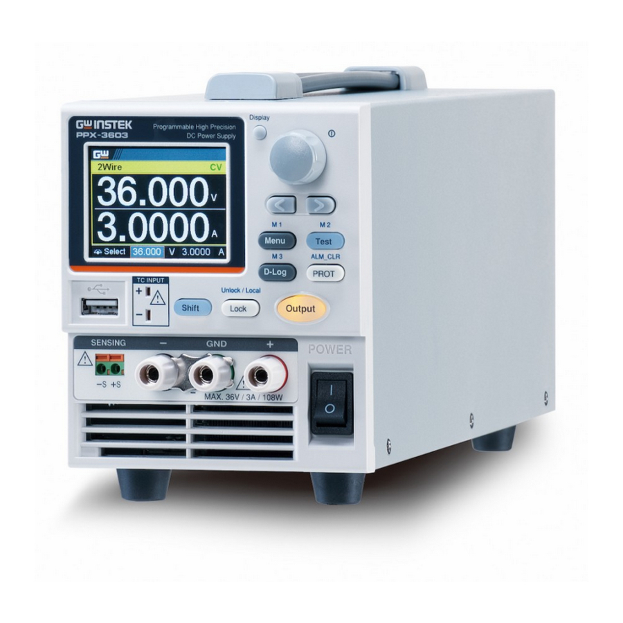
GETTING STARTED Appearance Front Panel Used to switch among 4 different Display display modes. Button Used to navigate menu, and to Knob Key configure or confirm voltage/current/time values, among others. Also, the indicator on the upper-right corner shows current state and power mode. - Page 12 PPX Series Programming Manual Used to select a parameter number in Left/Right the Function settings. Also the left Arrow Keys arrow key can be used as backspace. Used to enter the Menu page. Menu Button (+Shift) Used to recall the M1 setup.
- Page 13 GETTING STARTED Used to turn the output on or off. 10. Output Button USB A port for data transfer, loading 11. USB A Port test scripts and firmware update. Terminal to connect the K type 12. TC Input thermocouple cable for temperature measurement.
- Page 14 PPX Series Programming Manual DC output terminal for PPX is Binding Posts Terminal or European Type Jack Terminal. PPX-2002 the max. output is 20V/2A/40W DC output terminal for PPX is Binding Posts Terminal or European Type Jack Terminal. PPX-2005 the max. output...
-
Page 15: Display Area
GETTING STARTED Display Area 2-wire or 4-wire indicator. 2Wire/4Wire Displays the voltage. Voltage Meter Displays the current. Current Meter The scrolling symbol indicates to select V/A Set between V and A set via scrolling knob key. Guidance When the external CC or CV control is External CC &... - Page 16 CV mode nor CC mode, it shows UR instead. If it is not under power output, it simply shows Off. When PPX series connects to LAN network, the 11. LAN Indicator icon will be shown.
-
Page 17: Rear Panel
GETTING STARTED Rear Panel Remote-OUT RJ-45 connector that is used to daisy chain power supplies with the Remote-IN port to form a communication bus. Two different types of cables can be used for Remote-IN RS232 or RS485-based remote control. PSU-232: RS232 cable with DB9 connector kit. PSU-485: RS485 cable with DB9 connector kit. - Page 18 PPX Series Programming Manual GPIB connector for units equipped with IEEE GPIB programming option. (Factory Installed Options) External analog remote control connector. EXT I/O AC inlet. Line Voltage Input The AC selector is located at the AC Select bottom side of the unit.
-
Page 19: Theory Of Operation
GETTING STARTED Theory of Operation The theory of operation chapter describes the basic principles of operation, protection modes and important considerations that must be taken into account before use. Operating Description The PPX power supplies are regulated DC Background power supplies with a stable voltage and current output. -
Page 20: Cc And Cv Mode
PPX Series Programming Manual CC and CV Mode When the power supply is operating in CC and CV mode constant current mode (CC) a constant current Description will be supplied to the load. When in constant current mode the voltage output can vary, whilst the current remains constant. -
Page 21: Slew Rate
GETTING STARTED Conversely the power supply will operate in CC mode when the load resistance is less than the critical resistance. In CC mode the current output is equal to I and the voltage output is less than V Crossover >R point <R... -
Page 22: Bleeder Control
PPX Series Programming Manual High Speed Priority Slew rate = mode Enabled Bleeder Control The PPX DC power supplies employ a bleed Background resistor in parallel with the output terminals. Bleed Load resistor Bleed resistors are designed to dissipate the... -
Page 23: Alarms
GETTING STARTED By default the bleed resistance is on. For battery Note charging applications, be sure to turn the bleed resistance off as the bleed resistor can discharge the connected battery when the unit is off. Alarms The PPX power supplies have a number of protection features. When one of the protection alarms is set, the ALM icon on the display will be lit. -
Page 24: Considerations
PPX Series Programming Manual Considerations The following situations should be taken into consideration when using the power supply. When the power supply switch is first turned Inrush current on, an inrush current is generated. Ensure there is enough power available for the power... - Page 25 GETTING STARTED Current limit level Measured Ammeter current When the power supply is connected to a Reverse Current: regenerative load such as a transformer or Regenerative load inverter, reverse current will feed back to the power supply. The PPX power supply cannot absorb reverse current.
- Page 26 PPX Series Programming Manual When the power supply is connected to a load Reverse Current: such as a battery, reverse current may flow Accumulative energy. back to the power supply. To prevent damage to the power supply, use a reverse-current- protection diode in series between the power supply and load.
-
Page 27: Grounding
GETTING STARTED Grounding The output terminals of the PPX power supplies are isolated with respect to the protective grounding terminal. The insulation capacity of the load, the load cables and other connected devices must be taken into consideration when connected to the protective ground or when floating. - Page 28 PPX Series Programming Manual If the positive or negative terminal is connected Grounded output to the protective ground terminal, the terminal insulation capacity needed for the load and load cables is greatly reduced. The insulation capacity only needs to be greater than the maximum output voltage of the power supply with respect to ground.
-
Page 29: Remote Control
REMOTE CONTROL EMOTE CONTROL This chapter describes basic configuration of IEEE488.2 based remote control. Interface Configuration ........... 31 USB Remote Interface ................31 Configuration ..................31 USB CDC Function Check ..............32 GPIB Remote Interface ................39 Configuration ..................39 GPIB Function Check ................ - Page 30 PPX Series Programming Manual Status Register Overview ........130 Introduction to the Status Registers ............130 The Status Registers ...................131 Questionable Status Register Group ............132 Operation Status Register Group ............135 Standard Event Status Register Group ...........138 Status Byte Register & Service Request Enable Register .....140 Error List ..............
-
Page 31: Interface Configuration
REMOTE CONTROL Interface Configuration USB Remote Interface Configuration Type A, host PC side connector Configuration Rear panel Type B, slave PPX side connector 1.1 (full speed) Speed CDC (communications device USB Class class) 1. Connect the USB cable to the rear Steps panel USB B port. -
Page 32: Usb Cdc Function Check
PPX Series Programming Manual USB CDC Function Check To test the USB CDC functionality, National Background Instruments Measurement and Automation Explorer can be used. This program is available on the NI website, www.ni.com., via a search for the VISA Run-time Engine page, or “downloads”... - Page 33 REMOTE CONTROL 4. The Device Manager will show up CDC- WXXXXXX on “Other Devices”. 5. Select the CDC-WXXXXXX and click the right button of mouse to "Update Driver Software".
- Page 34 7. Indicate the driver folder to the system and then press "Next". And this folder should consist of below 2 files. The USB driver of PPX can be downloaded from Note download area of PPX on the GW Instek website http://www.gwinstek.com/en- global/Support/download...
- Page 35 REMOTE CONTROL 8. Windows 7 will install the driver for a while. 9. If everything works fine, you may get below message. And the COM53 is the USB CDC ACM port of PPX.
- Page 36 PPX Series Programming Manual 10. Double check the "Device Manager". The port should like below. Steps 1~10 are for the USB CDC Driver installation. 11. Start the NI Measurement and Automation Explorer (MAX) program. Using Windows, press: Start>All Programs>National Instruments>Measurement & Automation...
- Page 37 REMOTE CONTROL 12. From the Configuration panel access; My System>Devices and Interfaces>Network Devices 13. Click Open VISA Test Panel. 14. Click the Configuration icon, 15. Click on I/O Settings. 16. Make sure the Enable Termination Character check box is checked, and the terminal character is \n (Value: xA).
- Page 38 PPX Series Programming Manual 21. The *IDN? query will return the Manufacturer, model name, serial number and firmware version in the dialog box. GW-INSTEK,PPX-10H01,TW123456,V0.A4...
-
Page 39: Gpib Remote Interface
REMOTE CONTROL GPIB Remote Interface Configuration To use GPIB, the optional GPIB option (GW Instek part number: Option 1) must be installed. This is a factory installed option and cannot be installed by the end-user. Only one GPIB address can be used at a time. -
Page 40: Gpib Function Check
PPX Series Programming Manual GPIB Function Check To test the GPIB functionality, National Background Instruments Measurement and Automation Explorer can be used. This program is available on the NI website, www.ni.com., via a search for the VISA Run-time Engine page, or “downloads”... - Page 41 REMOTE CONTROL 4. Select the device (GPIB address of PPX) that now appears in the System>Devices and Interfaces > GPIB-USB-HS “GPIBX” node. 5. Click on the VISA Properties tab on the bottom. 6. Click Open Visa Test Panel.
- Page 42 PPX Series Programming Manual 7. Click on Configuration. 8. Click on the GPIB Settings tab and confirm that the GPIB settings are correct. 9. Click on the I/O Settings tab. 10. Make sure the Enable Termination Character check box is checked, and the terminal character is \n (Value: xA).
- Page 43 REMOTE CONTROL 12. Click on Input/Output. 13. Click on the Basic I/O tab. 14. Enter *IDN? in the Select or Enter Command drop down box. 15. Click Query. 16. The *IDN? query will return the Manufacturer, model name, serial number and firmware version in the dialog box.
-
Page 44: Uart Remote Interface
PPX Series Programming Manual For further details, please see the programming Note manual, available on the GW Instek web site @ www.gwinstek.com. UART Remote Interface Configure UART The PPX uses the IN & OUT ports for UART Overview communication coupled with RS232 (GW Instek part number: GTL-259) or RS485 adapters (GW Instek part number: GTL-260). - Page 45 REMOTE CONTROL RS485 cable with DB-9 Connector Remote IN Port Remarks DB9 & RJ-45 Pin No. Name Pin No. Name shielded Housing Shield Housing Shield connectors from GTL-260 TXD - RXD - Twisted connection kit pair TXD + RXD + RXD - TXD - Twisted...
-
Page 46: Uart Function Check
Serial number, and Firmware version in the following format. GW-INSTEK,PPX-10H01,TW123456,V0.A4 Manufacturer: GW-INSTEK Model number : PPX-10H01 Serial number : TW1234567 Firmware version : V0.A4 For further details, please see the programming Note manual, available on the GW Instek web site @ www.gwinstek.com. -
Page 47: Multiple Unit Connection
REMOTE CONTROL Multiple Unit Connection The PPX power supplies can have up to 31 units daisy-chained together using the 8 pin connectors (IN OUT ports) on the rear panel. The first unit in the chain is remotely connected to a PC using GTL-260 (RS485 cable with DB9 connector).Each subsequent unit is daisy-chained to the next using a RS485 local bus. -
Page 48: Multiple Units Function Check
PPX Series Programming Manual 4. Set the addresses and mode of all units using UART menu. It must be a unique address identifier and mode select is RS485. 5. Multiple units can be operated using SCPI commands now. See the programming manual or see the function check below for usage details. - Page 49 REMOTE CONTROL ADR is followed by address, which can be 0 to 31 and is used to access the power supply. Selects the unit with address 0 and returns its identity string. Also, sets its volt as 5 and returns its volt in 5. ADR 5 *IDN? GW-INSTEK,PPX-3601,TW654321,V0.A2...
-
Page 50: Error Message
PPX Series Programming Manual Error Message If an error is detected in command or query, the power supply will respond with an error message. Command Errors The command error bit in the standard Event Overview Status Register (ESR) is set to ‘1' when such an error occurs. -
Page 51: Execution Errors
REMOTE CONTROL Character data not allowed E-148 String data error E-150 Invalid string data E-151 String data not allowed E-158 Block data error E-160 Invalid block data E-161 Block data not allowed E-168 Expression error E-170 Invalid expression E-171 Expression data not allowed E-178 Macro error E-180... - Page 52 PPX Series Programming Manual Data corrupt or stale E-230 Data questionable E-231 Invalid format E-232 Invalid version E-233 Hardware error E-240 Hardware missing E-241 Mass storage error E-250 Missing mass storage E-251 Missing media E-252 Corrupt media E-253 Media full...
-
Page 53: Devic Specific Errors
REMOTE CONTROL Devic Specific Errors The device dependant error bit in the standard Overview Event Status Register (ESR) is set to '1' when such an error occurs. Error Code Description Device-specific error. E-300 System error. E-310 Memory error. E-311 PUD memory lost. E-312 Calibration memory lost. -
Page 54: Other Scpi Defined Error Values
PPX Series Programming Manual Other SCPI Defined Error Values The corresponding bit in the standard Event Status Overview Register (ESR) is set to ‘1' when such an event occurs. Error Code Description Power on. E-500 User request. E-600 Request control. -
Page 55: Configure Ethernet Connection
The PPX series supports both DHCP connections so the instrument can be automatically connected to an existing network or alternatively, network settings can be manually configured. -
Page 56: Web Server Remote Control Function Check
PPX Series Programming Manual 2. Turn On DHCP and Web Server settings. 3. The indicator will be shown when a remote connection has been established. Remote Control indicator It may be necessary to cycle the power or refresh Note the web browser to connect to a network. - Page 57 REMOTE CONTROL The web browser interface appears as follows. The web browser interface allows you to access the following: Network configuration settings Measurement setting Normal Function setting External Control setting Temperature Control setting Analog Control ...
-
Page 58: Sockets Server Configuration
PPX Series Programming Manual Sockets Server Configuration This configuration example will configure the Configuration PPX socket server. The following configuration settings will manually assign the PPX an IP address and enable the socket server. The socket server port number is fixed at 2268. -
Page 59: Socket Server Function Check
REMOTE CONTROL Socket Server Function Check To test the socket server functionality, National Background Instruments Measurement and Automation Explorer can be used. This program is available on the NI website, www.ni.com., via a search for the VISA Run-time Engine page, or “downloads”... - Page 60 PPX Series Programming Manual 4. Select Manual Entry of Raw Socket from the popup window. 5. Enter the IP address and the port number of the PPX. The port number is fixed at 2268. 6. Click the Validate button. 7. A popup will appear if a connection is successfully established.
- Page 61 REMOTE CONTROL 9. Next configure the Alias (name) of the PPX connection. In this example the Alias is: PPX_DC1 10. Click finish. 11. The IP address of the PPX will now appear under Network Devices in the configuration panel. Select this icon now.
- Page 62 PPX Series Programming Manual 12. Click Open VISA Test Panel. 13. Click the Configuration icon, 14. Click on I/O Settings. 15. Make sure the Enable Termination Character check box is checked, and the terminal character is \n (Value: xA). 16. Click Apply Changes.
- Page 63 REMOTE CONTROL 20. The *IDN? query will return the Manufacturer, model name, serial number and firmware version in the dialog box. GW-INSTEK,PPX-10H01,TW123456,V0.A4 For further details, please see the programming Note manual, available on the GW Instek web site @ www.gwinstek.com.
-
Page 64: Socket Server Examples
The following visual basic programming Background example uses the VISA COM 3.0 Type Library. The example will connect to the PPX series using the IP address of 172.15.5.133 over port 2268. The program will send the *IDN? to the PPX Series, print the return string and then... -
Page 65: C++ Example
REMOTE CONTROL C++ Example The following program creates a connection to Background the PPX series and sets the voltage to 3.3 volts and the current 1.5 amps. The voltage and current reading is then read back and the connection is closed. - Page 66 PPX Series Programming Manual...
-
Page 67: Labview Example
REMOTE CONTROL LabVIEW Example The following picture shows a LabView Background programming example for the PPX Series. -
Page 68: Command Syntax
PPX Series Programming Manual Command Syntax Partial compatibility IEEE488.2 Compatible Partial compatibility Standard SCPI, 1999 SCPI commands follow a tree-like structure, Command organized into nodes. Each level of the Structure command tree is a node. Each keyword in a SCPI command represents each node in the command tree. - Page 69 REMOTE CONTROL A query is a simple or Query compound command followed by a question mark (?). A parameter (data) is returned. meas:curr:dc? Example Two or more commands on Compound the same command line. Compound commands are separated with either a semi- colon (;) or a semi-colon and a colon (;:).
- Page 70 PPX Series Programming Manual Commands and queries have two different Command Forms forms, long and short. The command syntax is written with the short form of the command in capitals and the remainder (long form) in lower case. The commands can be written in capitals or lower-case, just so long as the short or long forms are complete.
- Page 71 REMOTE CONTROL integers 0, 1, 2, 3 <NR1> decimal 0.1, 3.14, 8.5 <NR2> numbers floating point 4.5e-1, 8.25e+1 <NR3> any of NR1, 2, 3 1, 1.5, 4.5e-1 <NRf> <block data> Definitive length arbitrary block data. A single decimal digit followed by data. The decimal digit specifies how many 8-bit data bytes follow.
-
Page 72: Command List
PPX Series Programming Manual Command List :ABORt ............... 76 Abort Command :APPLy ................ 76 Apply Commands :ADR ................77 Address Commands :INITiate:CONTinuous[:TRANsient] ....77 Initiate Commands :INITiate[:IMMediate]:NAME ....... 78 :INITiate[:IMMediate][:TRANsient] ..... 78 :MEMory:TRIGgered ..........79 Memory Commands :MEASure[:SCALar]:ALL[:DC] ......80 Measure :MEASure[:SCALar]:CURRent[:DC] .... - Page 73 REMOTE CONTROL :SENSe:AVERage:COUNt ........86 Sense Commands :SENSe:DLOG:SFOL ..........86 :SENSe:DLOG:STATe ........... 87 :SENSe:DLOG:PERiod .......... 87 :SENSe:AHOur:RESet ..........87 :SENSe:WHOur:RESet ..........87 :STATus:OPERation[:EVENt] ......88 Status Commands :STATus:OPERation:CONDition ......88 :STATus:OPERation:ENABle ....... 89 :STATus:OPERation:PTRansition ......89 :STATus:OPERation:NTRansition ....... 89 :STATus:QUEStionable[:EVENt] ......89 :STATus:QUEStionable:CONDition ....
- Page 74 PPX Series Programming Manual [:SOURce]:POWer[:LEVel][:IMMediate][:AMPLitu de] ................101 [:SOURce]:POWer:CONTrol ......... 101 :SYSTem:BEEPer[:IMMediate] ......103 System Commands :SYSTem:CONFigure:BEEPer[:STATe] ....104 :SYSTem:CONFigure:BLEeder[:STATe] ..... 104 :SYSTem:CONFigure:CURRent:CONTrol ..105 :SYSTem:CONFigure:VOLTage:CONTrol ..105 :SYSTem:CONFigure:OUTPut:PON[:STATe] .. 106 :SYSTem:CONFigure:OUTPut:EXTernal:MODE ..................107 :SYSTem:CONFigure:OUTPut:EXTernal[:STATe] ..................107 :SYSTem:CONFigure:TRIGger:INPut:SOURce 108 :SYSTem:CONFigure:TRIGger:INPut:LEVel ..108 :SYSTem:CONFigure:TRIGger:OUTPut:SOURce ..................
- Page 75 REMOTE CONTROL :SYSTem:COMMunicate:SERial[:RECeive] :TRAN smit:PARity ..............117 :SYSTem:COMMunicate:SERial[:RECeive] :TRAN smit:SBITs ..............117 :SYSTem:COMMunicate:USB:FRONt:STATe .. 118 :SYSTem:COMMunicate:USB:REAR:STATe..118 :SYSTem:ERRor ............118 :SYSTem:KLOCk ............. 119 :SYSTem:KEYLock:MODE ........119 :SYSTem:ERRor:ENABle ........119 :SYSTem:PRESet ............119 :SYSTem:VERSion ........... 119 :SYSTem:KEYBoard:BEEPer ........120 :SYSTem:CAPacity:AHOur ........120 :SYSTem:CAPacity:WHOur ........
-
Page 76: Abort
PPX Series Programming Manual Abort Command :ABORt ............... 76 :ABORt The :ABORt command will cancel any triggered Description actions. :ABORt Syntax Apply Commands :APPLy ............... 76 :APPLy Query The apply command sets the voltage and current Description at the same time. -
Page 77: Adr
REMOTE CONTROL Address Commands :ADR ................77 :ADR Query Sets or queries the RS485 interface address. Description Syntax :ADR <NR1> Query Syntax :ADR? 0~30 Parameter/ <NR1> Return parameter ADR 5 Example Sets the RS485 address 5. Initiate Commands :INITiate:CONTinuous[:TRANsient] ....77 :INITiate[:IMMediate]:NAME ...... -
Page 78: Initiate[:Immediate]:Name
PPX Series Programming Manual :INITiate[:IMMediate]:NAME The INITiate command starts the TRANsient or Description OUTPut trigger. Syntax :INITiate[:IMMediate]:NAME {TRANsient|OUTPut} Starts the TRANsient trigger. Parameter TRANSient Starts the OUTPut trigger. OUTPut Example INITiate:NAME TRANient Starts the TRANSient trigger. :INITiate[:IMMediate][:TRANsient] This command controls the enabling of output Description triggers. -
Page 79: Memory:triggered
REMOTE CONTROL Memory Commands :MEMory:TRIGgered ..........79 :MEMory:TRIGgered Query Description Sets or queries which memory is loaded when a trigger input is received and the trigger input is configured to load a memory setting. This is the equivalent to the TRIG Control menu (Trigin Memory)settings. -
Page 80: Measure[:Scalar]:All[:Dc]
PPX Series Programming Manual Measure Commands :MEASure[:SCALar]:ALL[:DC] ......80 :MEASure[:SCALar]:CURRent[:DC] ....80 :MEASure[:SCALar]:VOLTage[:DC] ....80 :MEASure[:SCALar]:POWer[:DC] ......81 :MEASure[:SCALar]:CURRent:RANGe ....81 :MEASure[:SCALar]:VOLTage:RANGe ..... 81 :MEASure:TEMPerature ......... 82 :MEASure[:SCALar]:ALL[:DC] Query Takes a measurement and returns the average Description output current and voltage... -
Page 81: Measure[:Scalar]:Power[:Dc]
REMOTE CONTROL :MEASure[:SCALar]:POWer[:DC] Query Takes a measurement and returns the average Description output power. Syntax :MEASure[:SCALar]:POWer[:DC]? Returns the power measured in watts. Return "+0.0000" :MEASure[:SCALar]:CURRent:RANGe Query Sets or queries the current measurement range. Description Syntax :MEASure[:SCALar]:CURRent:RANGe {<NR1>|AUTO|IH|IL|ILL} Query Syntax :MEASure[:SCALar]:CURRent:RANGe? AUTO|0 Current measurement auto range. -
Page 82: Measure:temperature
PPX Series Programming Manual :MEASure:TEMPerature Query Takes a measurement and returns the temperature. Description :MEASure:TEMPerature? Syntax “+0.0000” Returns the temperature in celsius or Return fahrenheit. Return -32768 Returns the temperature in INVAILD. -
Page 83: Output:delay:on
REMOTE CONTROL Output Commands :OUTPut:DELay:ON ..........83 :OUTPut:DELay:OFF ..........83 :OUTPut:MODE ............. 84 :OUTPut[:STATe][:IMMediate] ......84 :OUTPut[:STATe]:TRIGgered ......84 :OUTPut:PROTection:CLEar ....... 85 :OUTPut:PROTection:TRIPped ......85 :OUTPut:PROTection:WDOG[:STATe] .... 85 :OUTPut:PROTection:WDOG:DELay ....85 :OUTPut:DELay:ON Query Sets the Delay Time in seconds for turning the Description output on. -
Page 84: Output:mode
PPX Series Programming Manual :OUTPut:MODE Query Sets the PPX output mode. This is the equivalent to Description the Output menu (V-I Slew Rate Select) settings. Syntax :OUTPut:MODE {<NR1>|CVHS|CCHS|CVLS|CCLS} Return Syntax :OUTPut:MODE? CV high speed priority Parameter CVHS | 0 CC high speed priority... -
Page 85: Output:protection:clear
REMOTE CONTROL :OUTPut:PROTection:CLEar Clears over-voltage, over-current and over- Description temperature (OVP, OCP, OTP) protection circuits. It also clears the temperature short and sense protection circuit .The other alarm(WDOG, CAP, TEMP Monitor)also clears. Syntax :OUTPut:PROTection:CLEar :OUTPut:PROTection:TRIPped Query Queries the unit to see if a protection circuit has Description been tripped. -
Page 86: Sense Commands
PPX Series Programming Manual Sense Commands :SENSe:AVERage:COUNt ........86 :SENSe:DLOG:SFOL ..........86 :SENSe:DLOG:STATe ........... 87 :SENSe:DLOG:PERiod .......... 87 :SENSe:AHOur:RESet ..........87 :SENSe:WHOur:RESet ..........87 :SENSe:AVERage:COUNt Query Sets or queries the level of smoothing for the Description average setting. Syntax :SENSe:AVERage:COUNt {<NR1>|LOW|MIDDle|HIGH}... -
Page 87: Sense:dlog:state
REMOTE CONTROL :SENSe:DLOG:STATe Query Enables or disables the data logger setting. Description Syntax :SENSe:DLOG:STATe {<NR1>} Return Syntax :SENSe:DLOG:STATe? Disable data logger. Parameter Enable data logger.The data is stored in the USB storage when USB storage plug Enable data logger,The data is sent to the interface when the remote control read data. -
Page 88: Status Commands
PPX Series Programming Manual Status Commands For an overview of all the status registers, their associated register contents and the system diagram, please see the status overview on page 130 :STATus:OPERation[:EVENt] ......88 :STATus:OPERation:CONDition ......88 :STATus:OPERation:ENABle ....... 89 :STATus:OPERation:PTRansition ......89 :STATus:OPERation:NTRansition ....... -
Page 89: Status:operation:enable
REMOTE CONTROL :STATus:OPERation:ENABle Query Sets or queries the bit sum of the Operation Status Description Enable register. Syntax :STATus:OPERation:ENABle <NR1> Query Syntax :STATus:OPERation:ENABle? 0~32767 Parameter <NR1> 0~32767 Return parameter <NR1> :STATus:OPERation:PTRansition Query Sets or queries the bit sum of the positive Description transition filter of the Operation Status register. -
Page 90: Status:questionable:condition
PPX Series Programming Manual :STATus:QUEStionable:CONDition Query Queries the status (bit sum) of the Questionable Description Status register. This query will not clear the register. Query Syntax :STATus:QUEStionable:CONDition? 0~32767 Return parameter <NR1> :STATus:QUEStionable:ENABle Query Sets or queries the bit sum of the Questionable Description Status Enable register. -
Page 91: Status:questionable:ntransition
REMOTE CONTROL :STATus:QUEStionable:NTRansition Query Sets or queries the negative transition filter of the Description Questionable Status register. Syntax :STATus:QUEStionable:NTRansition <NR1> Query Syntax :STATus:QUEStionable:NTRansition? 0~32767 Parameter <NR1> 0~32767 Return parameter <NR1> :STATus:PRESet This command resets the ENABle register, the Description PTRansistion filter and NTRansistion filter on the Operation Status and Questionable Status Registers. -
Page 92: Source Commands
PPX Series Programming Manual Source Commands [:SOURce]:CURRent[:LEVel][:IMMediate] [:AMPLitude] ............. 92 [:SOURce]:CURRent[:LEVel]:TRIGgered [:AMPLitude] ............. 93 [:SOURce]:CURRent:LIMit:AUTO ...... 93 [:SOURce]:CURRent:PROTection:DELay ..94 [:SOURce]:CURRent:PROTection[:LEVel] ..94 [:SOURce]:CURRent:PROTection:TRIPped ..95 [:SOURce]:CURRent:SLEWrate:RISing ....95 [:SOURce]:CURRent:SLEWrate:FALLing ..96 [:SOURce]:MODE? ..........96 [:SOURce]:VOLTage[:LEVel][:IMMediate] [:AMPLitude] ............. 97 [:SOURce]:VOLTage[:LEVel]:TRIGgered [:AMPLitude] ............. -
Page 93: [:Source]:Current[:Level]:Triggered [:Amplitude]
REMOTE CONTROL Minimum current level. parameter Maximum current level. Example SOUR:CURR:LEV:IMM:AMPL? 1.0000 Returns the current level in amps. [:SOURce]:CURRent[:LEVel]:TRIGgered [:AMPLitude] Query Sets or queries the current level in amps when a Description software trigger has been generated. Syntax [:SOURce]:CURRent[:LEVel]:TRIGgered[:AMPLitude] {<NR2> (A)| MINimum|MAXimum} Query Syntax [:SOURce]:CURRent[:LEVel]:TRIGgered[:AMPLitude]? 0%~105% of the rated current output in amps. -
Page 94: [:Source]:Current:protection:delay
PPX Series Programming Manual [:SOURce]:CURRent:PROTection:DELay Query Sets the Delay Time for OCP in seconds. Description The delay is set to 0.05 by default. Syntax [:SOURce]:CURRent:PROTection:DELay {<NR2>|MINimum|MAXimum} Query Syntax [:SOURce]:CURRent:PROTection:DELay? 0.05~2.5 seconds Parameter <NR2> The maximum allowed delay time The minimum allowed delay time Returns the delay time in seconds Return parameter <NR2>... -
Page 95: [:Source]:Current:protection:tripped
REMOTE CONTROL [:SOURce]:CURRent:PROTection:TRIPped Query Returns the state of the current protection circuits. Description Query Syntax [:SOURce]:CURRent:PROTection:TRIPped? Returns protection status. Return parameter <bool> Example SOUR:CURR:PROT:TRIP? >0 The protection circuit has not been tripped. [:SOURce]:CURRent:SLEWrate:RISing Query Sets or queries the rising current slew rate. This is only Description applicable for CC slew rate priority (CCLS) mode. -
Page 96: [:Source]:Current:slewrate:falling
PPX Series Programming Manual [:SOURce]:CURRent:SLEWrate:FALLing Query Sets or queries the falling current slew rate. This is only Description applicable for CC slew rate priority (CCLS) mode. Syntax [:SOURce]:CURRent:SLEWrate:FALLing {<NR2>(A)|MINimum|MAXimum} Query Syntax [:SOURce]:CURRent:SLEWrate:FALLing? Per step is between 0.00001A/msec and Parameter <NR2>... -
Page 97: [:Source]:Voltage[:Level][:Immediate] [:Amplitude]
REMOTE CONTROL [:SOURce]:VOLTage[:LEVel][:IMMediate] [:AMPLitude] Query Sets or queries the voltage level in volts. Description Syntax [:SOURce]:VOLTage[:LEVel][:IMMediate][:AMPLitude] {<NR2>(V)|MINimum|MAXimum} Query Syntax [:SOURce]:VOLTage[:LEVel][:IMMediate][:AMPLitude]? 0~105% of the rated output voltage in volts. Parameter <NRf> Minimum voltage level Maximum voltage level Returns the voltage level in volts Return parameter <NR2>... -
Page 98: [:Source]:Voltage:limit:auto
PPX Series Programming Manual [:SOURce]:VOLTage:LIMit:AUTO Query Sets whether to limit the voltage setting so that it Description does not exceed the OVP setting or become lower than the UVL setting. If you enable the limit when the OVP setting is lower than the voltage setting, the OVP setting will be set to 105 % of the voltage setting. -
Page 99: [:Source]:Voltage:protection[:Level]
REMOTE CONTROL [:SOURce]:VOLTage:PROTection[:LEVel] Query Sets or queries the overvoltage protection level. Description Syntax [:SOURce]:VOLTage:PROTection[:LEVel] {<NR2>(V)|MINimum|MAXimum} Query Syntax [:SOURce]:VOLTage:PROTection[:LEVel]? Parameter/Return <NR2> Minimum: Vrated * 0.05 Maximum: Vrated * 1.1 Minimum OVP level Maximum OVP level Example SOUR:VOLT:PROT:LEV MAX Sets the OVP level to its maximum. [:SOURce]:VOLTage:PROTection:TRIPped Query Sets or queries the overvoltage protection level. -
Page 100: [:Source]:Voltage:slewrate:falling
PPX Series Programming Manual Per step is between 0.0001V/msec and Parameter <NR2> depend on the unit type: 0.1 /0.2 /0.36 /1 V/msec. Minimum rising voltage slew rate is 0.0001V/msec. Maximum: Depend on the unit type: 0.1 /0.2 /0.36 /1 V/msec. - Page 101 REMOTE CONTROL Sets remote sense 2 wire INTernal | 0 Sets remote sense 4 wire EXTernal | 1 Return parameter <NR1> Example SOUR:VOLT: SENS EXT Sets remote sense 4 wire. [:SOURce]:POWer[:LEVel][:IMMediate][:AM PLitude] Query Sets or queries the constant power level in watts. Description Syntax [:SOURce]:POWer[:LEVel][:IMMediate][:AMPLitude]...
- Page 102 PPX Series Programming Manual System Function Command :SYSTem:BEEPer[:IMMediate] ......103 :SYSTem:CONFigure:BEEPer[:STATe] ..... 104 :SYSTem:CONFigure:BLEeder[:STATe] .... 104 :SYSTem:CONFigure:CURRent:CONTrol ..105 :SYSTem:CONFigure:VOLTage:CONTrol ..105 :SYSTem:CONFigure:OUTPut:PON[:STATe] .. 106 :SYSTem:CONFigure:OUTPut:EXTernal:MODE ..................107 :SYSTem:CONFigure:OUTPut:EXTernal[:STATe] ..................107 :SYSTem:CONFigure:TRIGger:INPut:SOURce 108 :SYSTem:CONFigure:TRIGger:INPut:LEVel ... 108 :SYSTem:CONFigure:TRIGger:OUTPut:SOURce ..................108 :SYSTem:CONFigure:TRIGger:OUTPut:WIDTh ..................
-
Page 103: System:beeper[:Immediate]
REMOTE CONTROL it:PARity ..............117 :SYSTem:COMMunicate:SERial[:RECeive] :TRANsm it:SBITs ............... 117 :SYSTem:COMMunicate:USB:FRONt:STATe .. 118 :SYSTem:COMMunicate:USB:REAR:STATe ..118 :SYSTem:ERRor ............118 :SYSTem:KLOCk ............. 119 :SYSTem:KEYLock:MODE ........119 :SYSTem:ERRor:ENABle ........119 :SYSTem:PRESet ............. 119 :SYSTem:VERSion ..........119 :SYSTem:KEYBoard:BEEPer ......... 120 :SYSTem:CAPacity:AHOur........120 :SYSTem:CAPacity:WHOur........120 :SYSTem:CAPacity:MODE ........ -
Page 104: System:configure:beeper[:State]
PPX Series Programming Manual Example 1 :SYST:BEEP 10 **after a 2 second wait** :SYST:BEEP? >8 The first command turns the beeper on for 10 seconds. After 2 seconds the SYST:BEEP? query returns the remaining beeper time (8 seconds). Example 2 :SYST:BEEP? MAX >3600... -
Page 105: System:configure:current:control
REMOTE CONTROL :SYSTem:CONFigure:CURRent:CONTrol Query Sets or queries the CC control mode (local control Description (panel), external voltage control, external resistance control). Note: It can not be set when output on. Syntax :SYSTem:CONFigure:CURRent:CONTrol { <NR1>|NONE|VOLTage|RRISing } Query Syntax :SYSTem:CONFigure:CURRent:CONTrol? Description Parameter <NR1>... -
Page 106: System:configure:output:pon[:State]
PPX Series Programming Manual Returns the current control Return Parameter <NR1> configuration. :SYSTem:CONFigure:OUTPut:PON[:STATe] Query Sets the output state at power-on. This is the Description equivalent to the PWR On Config menu(Power On Status) settings. These settings only apply after the unit has been reset. -
Page 107: System:configure:output:external:mode
REMOTE CONTROL :SYSTem:CONFigure:OUTPut:EXTernal:MODE Query Sets the logic used to turn the output on or off Description when using an external contact. This is the equivalent to the EXT Control menu(Output Type)settings. Syntax :SYSTem:CONFigure:OUTPut:EXTernal:MODE {<NR1>|LOW|HIGH} Return Syntax :SYSTem:CONFigure:OUTPut:EXTernal:MODE? Active low Parameter LOW | 0 Active high HIGH | 1... -
Page 108: System:configure:trigger:input:source
PPX Series Programming Manual :SYSTem:CONFigure:TRIGger:INPut:SOURce Query Sets or queries what action will be performed on Description receiving a trigger.This is the equivalent to the TRIG Control menu(Trigin Action)settings. Syntax :SYSTem:CONFigure:TRIGger:INPut:SOURce {<NR1>|NONE|OUTPut|SETTing|MEMory} Query Syntax :SYSTem:CONFigure:TRIGger:INPut:SOURce? No input trigger. Parameter NONE | 0 Toggles the output on receiving a trigger. -
Page 109: System:configure:trigger:output:width
REMOTE CONTROL No output trigger. Parameter NONE | 0 Output trigger is generated by a change in OUTPut | 1 the output. SETTing | 2 Output trigger is generated when a setting is changed. MEMory | 3 Output trigger is generated when a memory setting is loaded. -
Page 110: System:configure:temperature:control
PPX Series Programming Manual Parameter <NR1> Sets the output trigger to active low. LOW | 0 Sets the output trigger to active high. High | 1 Returns the trigger output level. Return Parameter <NR1> :SYSTem:CONFigure:TEMPerature:CONTrol Query Sets or queries the temperature control (K-Type Description Thermocouple) on/off. -
Page 111: System:configure:temperature:output:safe
REMOTE CONTROL :SYSTem:CONFigure:TEMPerature:OUTPut:SAFE Query Sets or queries the temperature output safe on/off. Description Monitor the temperature when the output is turned on and turn off the output when the monitored temperature is reached.This is the equivalent to the Temperature menu (Output safe)setting.Note:The temperature control is turned on first. -
Page 112: System:configure:temperature:adjust
PPX Series Programming Manual :SYSTem:CONFigure:TEMPerature:ADJust Query Sets or queries the adjust temperature. This is the Description equivalent to the Temperature menu (Adjust)settings. Syntax :SYSTem:CONFigure:TEMPerature:ADJust {<NR2>|MINimum|MAXimum} Query Syntax :SYSTem:CONFigure:TEMPerature:ADJust? [MINimum|MAXimum] Parameter <NR2> -2.5(Celsius) / -4.5(Fahrenheit) MINimum 2.5(Celsius) / 4.5(Fahrenheit) MAXimum Returns the adjust temperature. -
Page 113: System:communicate:gpib[:Self]:Address
REMOTE CONTROL Returns the status of the selected mode. Return Parameter <bool> Example SYST:COMM:ENAB 1,USBC Turns the USB-CDC interface auto. Query Example SYST:COMM:ENAB? USBC Queries the USB-CDC state, returns 1 (USB-CDC is auto). :SYSTem:COMMunicate:GPIB[:SELF] :ADDRess Query Sets or queries the GPIB address. Note: the setting Description will only be valid after the power has been cycled. -
Page 114: System:communicate:lan:gateway
PPX Series Programming Manual :SYSTem:COMMunicate:LAN:GATeway Query Sets or queries the Gateway address. Note: the Description setting will only be valid after the power has been cycled. Syntax :SYSTem:COMMunicate:LAN:GATeway <string> Query Syntax :SYSTem:COMMunicate:LAN:GATeway? Gateway address in string format ( “address”) Parameter/Return <string>... -
Page 115: System:communicate:lan:dhcp
REMOTE CONTROL :SYSTem:COMMunicate:LAN:DHCP Query Turns DHCP on/off. Queries the DHCP status. Description Note: the setting will only be valid after the power has been cycled. Syntax :SYSTem:COMMunicate:LAN:DHCP {<bool>|OFF|ON} Query Syntax :SYSTem:COMMunicate:LAN:DHCP? DHCP off Parameter OFF | 0 DHCP on ON | 1 Returns the DHCP status. -
Page 116: System:communicate:tcpip:control
PPX Series Programming Manual All keys are invalid. The instrument can only RWLock be controlled remotely. Example :SYST:COMM:RLST LOCAL Sets the operating mode to local. :SYSTem:COMMunicate:TCPip:CONTrol Query Queries the socket port number. Description Query Syntax :SYSTem:COMMunicate:TCPip:CONTrol? 0000 ~ 9999 Return parameter <NR1>... -
Page 117: It:parity
REMOTE CONTROL Syntax :SYSTem:COMMunicate:SERial[:RECeive]:TRANsmit :BITS <NR1> :SYSTem:COMMunicate:SERial[:RECeive]:TRANsmit Query Syntax :BITS? Parameter/Return <NR1> 7 bits parameter 8 bits Example SYST:COMM:SER:TRAN:BITS? >1 Indicates that 8 data bits are used for the UART connection. :SYSTem:COMMunicate:SERial[:RECeive] :TRANsmit:PARity Query Sets or queries the parity of the UART connection. Description Note: the setting will only be valid after the power has been cycled. -
Page 118: System:communicate:usb:front:state
PPX Series Programming Manual Syntax :SYSTem:COMMunicate:SERial[:RECeive]:TRANsmit :SBITs<NR1> :SYSTem:COMMunicate:SERial[:RECeive]:TRANsmit Query Syntax :SBITs? 1 stop bit Parameter/Return 2 stop bits parameter Example SYST:COMM:SER:TRAN:SBITs? >1 Indicates that one stop bit is used for the UART connection. :SYSTem:COMMunicate:USB:FRONt:STATe Query Queries the front panel USB-A port state. -
Page 119: System:klock
REMOTE CONTROL :SYSTem:KLOCk Query Enables or disables the front panel key lock. Description Syntax :SYSTem:KLOCk {<bool>|OFF|ON } Query Syntax :SYSTem:KLOCk? Panel keys unlocked Parameter OFF | 0 Panel keys locked ON | 1 Returns the key lock status. Return parameter <bool> :SYSTem:KEYLock:MODE Query Sets or queries the keylock mode. -
Page 120: System:keyboard:beeper
PPX Series Programming Manual Query Syntax :SYSTem:VERSion? <string> Returns Return the SCPI version as a string. Query Example SYST:VERS? >1999.9 :SYSTem:KEYBoard:BEEPer Query Sets or queries the keyboard buzzer state on/off. Description This is the equivalent to the Buzzer menu (Keyboard)settings. -
Page 121: System:capacity:mode
REMOTE CONTROL Syntax :SYSTem:CAPacity:WHOur {<NR2>|MINimum|MAXimum} Query Syntax :SYSTem:CAPacity:WHOur? [MINimum|MAXimum] 0.001~999999999.999 Parameter <NR2> 0.001 MINimum 999999999.999 MAXimum Returns the Watt-hour capacity. Return Parameter <NR2> :SYSTem:CAPacity:MODE Query Sets or queries the capacity mode. This is the Description equivalent to the AH/WH Meter menu (Mode) settings. - Page 122 PPX Series Programming Manual Fetch Commands :FETCh:AHOur? ............122 :FETCh:WHOur? ............122 :FETCh:AHOur? Query Queries the measurement of Ampere-hour Description capacity. Note: Install the license first. Query Syntax :FETCh:AHOur? Returns the the measurement of Ampere - Return Parameter <NR1> hour capacity.
- Page 123 REMOTE CONTROL Trigger Commands :TRIGger:OUTPut:SOURce ........123 :TRIGger:OUTPut[:IMMediate] ......123 :TRIGger[:TRANsient]:SOURce ......124 :TRIGger[:TRANsient][:IMMediate] ....124 Trigger Command Examples ......... 125 :TRIGger:OUTPut:SOURce Query Sets or queries the trigger source of the output Description trigger. Syntax :TRIGger:OUTPut:SOURce {BUS|IMMediate|EXTernal} Query Syntax :TRIGger:OUTPut:SOURce? Output trigger is generated by the bus.
- Page 124 PPX Series Programming Manual :TRIGger[:TRANsient]:SOURce Query Sets or queries the source of the transient trigger. Description Syntax :TRIGger[:TRANsient]:SOURce {BUS|IMMediate|EXTernal} Query Syntax :TRIGger[:TRANsient]:SOURce? Transient trigger is generated by the bus. Parameter/ Transient trigger is immediately Return parameter IMMediate generated. EXTernal The transient trigger is generated when an external signal triggers it.
- Page 125 REMOTE CONTROL Trigger Command Examples 1. The transient system for the trigger in immediate mode. Example 1 TRIG:TRAN:SOUR IMM CURR:TRIG MAX VOLT:TRIG 5 INIT:NAME TRAN <==The current changes to the maximum, and the voltage changes to 5V. 2. The transient system for the trigger in BUS mode. Example 2 TRIG:TRAN:SOUR BUS CURR:TRIG MAX...
- Page 126 PPX Series Programming Manual IEEE 488.2 Common Commands *CLS ................126 *ESE ................126 *ESR ................127 *IDN ................127 *OPC ................127 *RCL ................128 *RST ................128 *SAV ................128 *SRE ................128 *STB................129 *TRG ................129 *TST................
- Page 127 REMOTE CONTROL *ESR Query Queries the Standard Event Status (Event) register. Description The Event Status register is cleared after it is read. Query Syntax *ESR? Returns the bit sum of the Standard Event Return parameter <NR1> Status (Event) register and clears the register. *IDN Query Queries the manufacturer, model name, serial...
-
Page 128: Rcl
PPX Series Programming Manual *RCL Recalls the contents stored in memory slot M1 ~ Description M10. Syntax *RCL {<NR1>|MAX|MIN} 0 ~ 9 (as memory M1 ~ M10) Parameter <NR1> Recalls the M1 memory contents. Recalls the M10 memory contents. *RST Performs a device reset. -
Page 129: Stb
REMOTE CONTROL Returns the bit sum of the Service Request Return parameter <NR1> Enable register. *STB Query Queries the bit sum of the Status Byte register with Description MSS (Master summary Status) replacing the RQS bit (bit 6). Query Syntax *STB? Returns the bit sum of the Status Byte register Return parameter <NR1>... -
Page 130: Status Register Overview
Overview status of the power supply. The status registers maintain the status of the protection conditions, operation conditions and instrument errors. The PPX Series have a number of register groups: Questionable Status Register Group Standard Event Status Register Group Operation Status Register Group... - Page 131 REMOTE CONTROL The Status Registers...
- Page 132 PPX Series Programming Manual Questionable Status Register Group The Questionable Status Register Group Overview indicates if any protection modes or limits have been tripped. Bit Summary Event Bit # Weight OV (Over-Voltage) Over voltage protection has been tripped OC (Over-Current)
- Page 133 REMOTE CONTROL OTP(Over Temperature Protection) Over temperature protection has been tripped TSH(Temperature Short) K-Type thermocouple short. TM(Temperature Monitor) Temperature monitor reached. VL (Voltage Limit) Voltage limit has been reached CL (Current Limit) Current limit has been reached SD (Shutdown Alarm) 2048 PL (Power-Limit) 4096...
- Page 134 PPX Series Programming Manual The PTR/NTR (Positive/Negative transition) PTR/NTR Filters register determines the type of transition conditions that will set the corresponding bit in the Event Registers. Use the Positive transition filter to view events that change from false to...
- Page 135 REMOTE CONTROL Operation Status Register Group The Operation Status Register Group indicates Overview the operating status of the power supply. Bit Summary Event Bit # Weight CAL (Calibration mode) Indicates if the PPX is in calibration mode. LOCK (Key Lock) Keyboard locked.
- Page 136 PPX Series Programming Manual WTG (Waiting for trigger) Indicates if the PPX is waiting for a trigger. CV (Constant voltage mode) Indicates if the PPX is in CV mode. CP (Constant power mode) Indicates if the PPX is in CP mode.
- Page 137 REMOTE CONTROL The PTR/NTR (Positive/Negative transition) PTR/NTR Filters register determines the type of transition conditions that will set the corresponding bit in the Event Registers. Use the Positive transition filter to view events that change from false to positive, and use the negative transition filter to view events that change from positive to negative.
- Page 138 PPX Series Programming Manual Standard Event Status Register Group The Standard Event Status Register Group Overview indicates if any errors have occurred. The bits of the Event register are set by the error event queue. Bit Summary Event Bit #...
- Page 139 REMOTE CONTROL QUE (Query Error) The Query Error bit is set in response to an error reading the Output Queue. This can be caused by trying to read the Output Queue when there is no data present. DDE (Device Dependent Error) Device specific error.
- Page 140 PPX Series Programming Manual Status Byte Register & Service Request Enable Register The Status Byte register consolidates the status Overview events of all the status registers. The Status Byte register can be read with the *STB? query and can be cleared with the *CLS command.
- Page 141 REMOTE CONTROL MAV (Message Available) This is set when there is data in the Output Queue waiting to be read. (ESB) Event Summary Bit. The ESB is the summary bit for the Standard Event Status Register group. MSS Bit The MSS Bit is the summary of the Status Byte Register and Service Request register (bits 1-5, 7).
-
Page 142: Error List
PPX Series Programming Manual Error List Command Errors ............142 Execution Errors ............146 Device Specific Errors ..........148 Query Errors ............. 149 Command Errors Overview An <error/event number> in the range [ -199 , - 100 ] indicates that an IEEE 488.2 syntax error has been detected by the instrument’s parser. - Page 143 REMOTE CONTROL Error Code Description This is the generic syntax error for devices that -100 Command Error cannot detect more specific errors. This code indicates only that a Command Error as defined in IEEE 488.2,11.5.1.1.4 has occurred. An unrecognized command or data type was -102 Syntax error encountered;...
- Page 144 PPX Series Programming Manual The header contains more that twelve -112 Program characters (see IEEE 488.2, 7.6.1.4.1). mnemonic too long The header is syntactically correct, but it is -113 Undefined header undefined for this specific device; for example, *XYZ is not defined for any device.
- Page 145 REMOTE CONTROL Either the character data element contains an -141 Invalid invalid character or the particular element character data received is not valid for the header. A legal character data element was encountered -148 Character where prohibited by the device. data not allowed A string data element was expected, but was -151 Invalid string...
- Page 146 PPX Series Programming Manual Execution Errors Overview An <error/event number> in the range [ -299 , - 200 ] indicates that an error has been detected by the instrument’s execution control block. The occurrence of any error in this class shall cause the execution error bit (bit 4) in the event status register (IEEE 488.2, section 11.5.1) to be...
- Page 147 REMOTE CONTROL Indicates that a command is not executable -201 Invalid while while the device is in local due to a hard local in local control (see IEEE 488.2, 5.6.1.5); for example, a device with a rotary switch receives a message which would change the switches state, but the device is in local so the message cannot be executed.
- Page 148 PPX Series Programming Manual Indicates that a legal program data element was -222 Data out of parsed but could not be executed because the range interpreted value was outside the legal range as defined by the device (see IEEE 488.2, 11.5.1.1.5.).
- Page 149 REMOTE CONTROL or query errors; see the other error definitions in this section. Error Code Description Indicates that some error, termed “system -310 System error error” by the device, has occurred. This code is device-dependent. Indicates that the firmware detected a fault -320 Storage fault when using data storage.
- Page 150 PPX Series Programming Manual Error Code Description This is the generic query error for devices that -400 Query error cannot detect more specific errors. This code indicates only that a Query Error as defined in IEEE 488.2, 11.5.1.1.7 and 6.3 has occurred.
-
Page 151: Appendix
PPX Series Programming Manual PPENDIX PPX Series Default Settings The following default settings are the factory configuration settings for the power supply. Initial Default Setting Output LOCK Disabled Voltage Set 0.000 V Current Set 0.0000 A Output Default Setting Output On Dly(Delay) 00(hour):00(minute):00.00(sec) - Page 152 PPX Series Programming Manual EXT (External) Control Default Setting CV Control Front Panel CC Control Front Panel Output Type High Output Enable TRIG(Trigger Control) Default Setting Trigin Level High Trigin Action None Trigin Voltage 0.000 V Trigin Current 0.0000 A...
- Page 153 APPENDIX Utility - Buzzer Default Setting Protect Keyboard Utility - Bleeder Default Setting Bleeder APP - AH/WH Meter (License Key) Default Setting Mode Disable AHour 999999999.999 Ah WHour 999999999.999 Wh Protect Default Setting Voltage Limit 0.000 V OVP Level 1.1 X Vrate Current Limit OCP Level 1.1 X Irate)
-
Page 154: Index
PPX Series Programming Manual NDEX Accessories ........9 Rear panel diagram ....17 Alarm Remote control ......29 description ........23 Command list ....... 72 Command syntax ......68 Bleeder control Error list ........142 description ........22 Ethernet configuration ....55 Caution symbol ......
Need help?
Do you have a question about the PPX Series and is the answer not in the manual?
Questions and answers