dji Robomaster EP Core User Manual
Hide thumbs
Also See for Robomaster EP Core:
- Programming manual (187 pages) ,
- Quick start manual (62 pages) ,
- Disclaimer and safety manuallines (19 pages)
Table of Contents
Advertisement
Advertisement
Table of Contents

Related Manuals for dji Robomaster EP Core


Summary of Contents for dji Robomaster EP Core
- Page 1 User Manual v1.0 2020.08...
- Page 2 Navigating to a Topic View a complete list of topics in the table of contents. Click on a topic to navigate to that section. Printing this Document This document supports high resolution printing. © 2020 DJI All Rights Reserved.
-
Page 3: Using This User Manual
Check to make sure all parts are included and prepare for assembly by reading the RoboMaster EP Core Quick Start Guide. Refer to this user manual for more information. Watch all tutorial videos and read the RoboMaster EP Core Safety Guidelines and Disclaimer before using for the first time. Watching the Video Tutorials Visit the official DJI website https://www.dji.com/robomaster-ep-core/video or go to the app and... -
Page 4: Table Of Contents
Contents Using this User Manual Legends Before Use Watching the Video Tutorials Referring to the RoboMaster EP Core Programming Manual Using an SDK Contents Product Profile Introduction Robot Diagram Overview Preparing Modules and Functions Using the RoboMaster App Omnidirectional Chassis... - Page 5 ROBOMASTER EP Core User Manual Operating Your Robot Checking Before Use Powering on the Battery Operating the Robot Using a Mobile Device Gameplay Operating the Robot Using a Gamepad Using a Computer and RoboMaster Appendix Specifications Firmware Update Calibrating the Robot...
-
Page 6: Product Profile
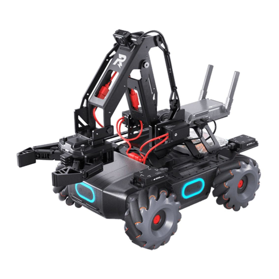
5. Chassis Left Armor (built-in Hit Detector) 14. Gripper 6. Chassis Extension Platform 15. Camera 7. Servo 16. Intelligent Controller 8. Robotic Arm (1 of 2) 17. Intelligent Controller Antenna 9. Robotic Arm Connecting Rod #1 18. Rear Extension Platform © 2020 DJI All Rights Reserved. -
Page 7: Overview
The robot is also compatible with third-party building blocks, providing even more ways to learn and have fun. Open DJI SDK is available on the robot and supports 39 programmable sensor ports. It is also compatible with third-party hardware, providing users with unlimited creative possibilities. - Page 8 QR code to download the app on your mobile device. B. Users can also download the RoboMaster software for Windows or Mac from the official DJI website to control the robot with a keyboard and mouse. Windows: https://www.dji.com/robomaster_app Mac: https://www.dji.com/robomaster_app Use your DJI account to log in to the RoboMaster app.
- Page 9 Refer to the Connecting section for more information. Initializing the Robot with the App Activating the Robot After connecting, use your DJI account to activate the robot in the RoboMaster app. Activation requires an internet connection. 1. Start activation. 2. Follow the prompts to complete activation.
- Page 10 ROBOMASTER EP Core User Manual Motor Addressing Motor addressing is required in the app before using for the first time. Follow the prompts to complete motor addressing. 1. Start Motor Addressing. 2. Lift the chassis and follow the prompts to rotate the Mecanum wheels in the order shown onscreen until all wheels have been rotated.
- Page 11 ROBOMASTER EP Core User Manual 4. Motor addressing completed. Motor addressing is required when a motor is replaced. Open the RoboMaster app, click Settings then System, and select Motor Addressing. Armor Addressing Armor addressing is required in the app when using the robot for the first time. Follow the prompts to complete armor addressing.
- Page 12 ROBOMASTER EP Core User Manual 3. Armor addressing completed. Armor addressing is required when an armor module is replaced. Go to the RoboMaster app, click Settings, then System, and select Armor Addressing. Robotic Arm Installation The robotic arm must be installed in the app before using the robot for the first time.
- Page 13 ROBOMASTER EP Core User Manual 3. Calibrate the robotic arm. Gripper Installation The gripper must be installed before using the robot for the first time. Servo Installation Make sure that the servos installed to the robot have different IDs and each ID ranges from 1 to 3.
- Page 14 ROBOMASTER EP Core User Manual 2. Follow the prompts to connect the servos in turn. 3. Follow the prompts to select module numbers for the servos until each servo has its unique number. Servos can be connected in series. After removing the robotic arm, the two servos on the robotic arm can be controlled separately.
- Page 15 ROBOMASTER EP Core User Manual 2. Follow the prompts to connect the infrared distance sensors in turn. 3. Follow the prompts to select module numbers for the infrared distance sensors until each sensor has its unique number. The robot supports the installation of multiple infrared distance sensors and users can select the ID accordingly.
-
Page 16: Modules And Functions
Product Support: Tap to enter the official DJI product support page. b. Maintenance Support: Tap to enter the official DJI Repair Center page. c. User Manuals: Tap to enter the official DJI user manual download page. d. Vision Markers: Tap to enter the official Vision Marker download page. - Page 17 ROBOMASTER EP Core User Manual 5. Connect The robot must be connected with the app. Tap to see a guide on how to connect via Wi-Fi or router. Connection via Wi-Fi Users can enter both Solo and Battle mode when connecting via Wi-Fi.
- Page 18 ROBOMASTER EP Core User Manual Resetting the Password Users can enter both Solo and Battle mode when connecting via router. Follow the steps below to connect: (1). Slide the mode switch on the intelligent controller to and power on the robot.
- Page 19 The RoboMaster EP Core Programming Manual offers detailed explanations of various blocks and modules, making it easier for users to understand the fundamentals of EP Core programming.
-
Page 20: Omnidirectional Chassis
ROBOMASTER EP Core User Manual EP Core cannot use the blaster, gimbal, or their related functions in Solo, Battle, or Lab mode. It is recommended to connect the blaster or gimbal first. Omnidirectional Chassis Introduction The chassis is an omnidirectional motion platform based on the Mecanum wheels, which can be used to move forward, traverse, skew, rotate, or a combination of movements at once. - Page 21 ROBOMASTER EP Core User Manual 2. Power Port Power port used for intelligent battery connection. Note that this interface contains the battery management system. Avoid unplugging the power port unless necessary. 3. M BUS Port Motor port used for motor connection.
- Page 22 ROBOMASTER EP Core User Manual Connect the black, orange, and red cables to the ports of the corresponding color. Make sure the motion controller is properly installed before use and the screws on the chassis rear cover are locked. After each reinstallation of the motion controller, calibrate the robot if prompted to do so in the RoboMaster app.
-
Page 23: Intelligent Controller
ROBOMASTER EP Core User Manual Armor Modules A total of four armored modules are installed on the four sides of the chassis, which protect the internal structure of the robot. Each hit detector module is represented by an LED light and is visible under the armor module. -
Page 24: Camera
DO NOT pull on the antenna. If the intelligent controller antenna is damaged, the performance of the robot will be affected. Contact DJI if the antenna is damaged. Camera The camera features a 1/4-inch sensor with 5 million pixels and a FOV of 120°, allowing users to control the robot from a first-person perspective. -
Page 25: Intelligent Battery
ROBOMASTER EP Core User Manual Intelligent Battery The intelligent battery has a capacity of 2400 mAh, a voltage of 10.8 V, and a variety of power management functions. LED2 LED3 LED1 LED4 1. Power Button 2. Battery Level Indicator Intelligent Battery Functions 1. - Page 26 Charging will resume when the temperature falls within the normal range. DJI is not responsible for damage caused by third-party chargers. © 2020 DJI All Rights Reserved.
- Page 27 ROBOMASTER EP Core User Manual Mounting the Intelligent Battery When in use, open the rear armor cover and insert the battery into the battery compartment. Make sure the battery is securely installed. Otherwise, the battery may fall out or have insufficient contact, which can lead to loss of battery information.
-
Page 28: Robot Led Indicator Description
ROBOMASTER EP Core User Manual Powering On/Off Press and hold the power button for more than two seconds to power on or off. Low-Temperature Notice 1. The performance of the intelligent battery is significantly reduced at temperatures below 5° C (41° F). -
Page 29: Servo
The servo will perform a self-test when it is powered on. If a self-test error occurs, reconnect the servo with the power supply. Contact DJI Support if the servo still does not work normally after being powered on multiple times. -
Page 30: Robotic Arm And Gripper
ROBOMASTER EP Core User Manual When in use, DO NOT touch the servo to avoid injury. DO NOT hit the servo. Otherwise, it may reduce the service life of the servo or even lead to permanent damage. When the servo overload warning prompts appear in the app multiple times, stop the operation immediately and check the operation and the structure of the robotic arm or servo. -
Page 31: Power Connector Module
ROBOMASTER EP Core User Manual Power Connector Module Introduction A power connector module can connect and power third-party hardware, offering multiple ports to connect hardware and create custom programs and applications. 1. 12V Power Input Port 4. 5V/4A Power Output Port The input voltage is 9.6-12.6 V. - Page 32 ROBOMASTER EP Core User Manual 2. Connect the power cable and a Y-cable. 3. After connecting a Y-cable to the motion controller as shown below, place the power cable on the chassis and pull the XT30 power cable of a Y-cable through the chassis middle frame to the chassis cabin.
- Page 33 ROBOMASTER EP Core User Manual 5. As shown below, connect the XT30 power cable in the chassis cabin to the 12V power input port and the B end of the 12cm data cable to the CAN bus port of the power connector module.
-
Page 34: Infrared Distance Sensor (Tof)
ROBOMASTER EP Core User Manual Infrared Distance Sensor (TOF) Introduction The infrared distance sensor calculates the distance between a sensor and an object by measuring the time it takes an infrared light to reach the object and return to the sensor. The infrared distance sensor consists of an illumination unit, optical receiver, and signal processing system. - Page 35 ROBOMASTER EP Core User Manual Left side: 2. Use two M3-D screws to fix the TOF module to the left side of the extension platform, located above the chassis left armor. 3. As shown below, connect the TOF module with the power connector module with a 14cm data cable.
- Page 36 ROBOMASTER EP Core User Manual 5. After removing the screws of the right armor, connect the TOF module with the right armor with a 12cm data cable. 12 cm Infrared Armor data distance cable sensor data cable 6. Arrange the data cable as shown below and remount the right armor.
- Page 37 ROBOMASTER EP Core User Manual 8. Use two M3-C screws to fix the straight connecting rod to the front of the extension platform. 9. As shown below, connect the TOF module with the power connector module with a 14cm data cable.
- Page 38 ROBOMASTER EP Core User Manual Communicate with the infrared distance sensor by sending a plaintext string via the serial. Below shows the control commands that the infrared distance sensor supports: Description Control Command Turn on the infrared distance sensor “ir_distance_sensor measure on”...
-
Page 39: Sensor Adapter
ROBOMASTER EP Core User Manual Sensor Adapter Introduction The robot is equipped with four sensor adapters, with IDs set to 1 by default. Each sensor adapter has two sensor ports and provides a power supply, making it convenient to connect and power third-party sensors that measure inputs such as temperature, pressure, and distance. - Page 40 ROBOMASTER EP Core User Manual 2. After removing the screws of the left armor and right armor, connect the respective sensor adapters with the armors using two 12cm data cables. 12 cm Sensor adapter Armor data cable Armor data Sensor...
- Page 41 ROBOMASTER EP Core User Manual 5. As shown below, connect the sensor adapter with the power connector module with two 14cm data cables. 14 cm LED Indicator for Sensor Adapter The LED indicator is used to indicate the status of the sensor adapter. Details are as follows:...
-
Page 42: Straight Connecting Rod
ROBOMASTER EP Core User Manual Straight Connecting Rod The straight connecting rod can be fixed to the chassis extension platform so that an infrared distance sensor or camera can be installed. Below shows the installation procedure for the camera. 1. Use two M3-C screws to fix the camera to the specific position of the straight connecting rod as shown below. -
Page 43: Front Axle Extension Platform
ROBOMASTER EP Core User Manual Front Axle Extension Platform The front axle extension platform can be fixed to the front of the chassis so that a gripper or sensor can be installed. Below shows the installation procedure for the gripper. -
Page 44: Robot And Third-Party Platforms
ROBOMASTER EP Core User Manual Robot and Third-Party Platforms The robot is compatible with third-party platforms. Third-party platforms are powered by the power connector module and communicate with the robot using the SDK protocol. For more information, visit robomaster-dev.rtfd.io. There are two ways to connect the robot with third-party platforms:... - Page 45 ROBOMASTER EP Core User Manual b) USB Connection The third-party platform Raspberry Pi connects with the power connector module and communicates with the robot via the USB port of the intelligent controller as shown below: The third-party platform Jetson Nano...
-
Page 46: Gamepad (Not Included)
ROBOMASTER EP Core User Manual Gamepad (Not Included) Introduction By connecting to a mobile device running the RoboMaster app, users can control the robot and perform multiple tasks with the gamepad and app. Additionally, a mouse can be connected to the gamepad for more precision control of the robot. - Page 47 ROBOMASTER EP Core User Manual Firmware Update The firmware of the gamepad can be updated using the RoboMaster app. When there is a firmware update available, the RoboMaster app will send a prompt after the gamepad is connected. Follow the prompts to update the firmware.
-
Page 48: Operating Your Robot
It is recommended to use the robot on flat surfaces such as wooden floors and carpets. Uneven surfaces such as sand or rocks may damage the wheels or motors. Using Solo Mode Enter Solo mode to see the page below. © 2020 DJI All Rights Reserved. - Page 49 ROBOMASTER EP Core User Manual 1. Back button: Tap to return to the home page. 2. Solo mode games button: Tap to enter Target Practice or Target Race. 3. Connection status button: Tap to see how to connect the Robot and the app.
- Page 50 ROBOMASTER EP Core User Manual Operating the Robot The camera view is mainly used to control the chassis, robotic arm, gripper of the robot. Controlling the Chassis Tap the chassis control button to move the robot forward, backward, or sideward.
-
Page 51: Gameplay
The control stick on the gamepad is used to control the chassis. The mouse actions are listed below, which can also be performed by the app, but the mouse is the primary controller. Mouse Action Robot Action Right click Zooms in Move mouse Controls the chassis © 2020 DJI All Rights Reserved. -
Page 52: Using A Computer And Robomaster
Installing the Windows or Mac Version of RoboMaster 1. Users can download the RoboMaster app for Windows or Mac from the official DJI website on a computer to control the robot with a keyboard and mouse. -
Page 53: Lab
The RoboMaster app Lab offers hundreds of programming blocks that allow you to access features such as PID control. The RoboMaster EP Core Programming Manual provides instructions and examples to help users quickly learn programming techniques for controlling the robot. - Page 54 ROBOMASTER EP Core User Manual 1. Scratch page: Tap to view Scratch programs. 2. Python page: Tap to view Python programs. 3. Import DSP file: This function is available on Android, Windows, and Mac devices. DSP files can be imported to iOS devices by using AirDrop.
- Page 55 AI Modules There are six AI modules that can be programmed by entering Lab then DIY Programming then Scratch. Refer to the Smart section of the RoboMaster EP Core Programming Manual for more programming examples. Note that the AI module will be affected in the following situations: a.
- Page 56 Program or a Custom Skill and run on the robot. Users can also convert Scratch programs into Python code and use the source code display to help get started with programming with Python. Refer to the RoboMaster EP Core Programming Manual for more information.
-
Page 57: Appendix
FCC, 2.4 GHz 190 m, 5.8 GHz 300 m CE, 2.4 GHz 180 m, 5.1 GHz 70 m SRRC, 2.4 GHz 180 m, 5.8 GHz 300m MIC, 2.4 GHz 180 m Transmission Standard IEEE802.11a/b/g/n © 2020 DJI All Rights Reserved. - Page 58 ROBOMASTER EP Core User Manual Camera Sensor CMOS 1/4”; Effective pixels: 5MP 120° Max Still Photo Resolution 2560×1440 pixels FHD: 1080p/30fps Max Video Resolution HD: 720p/30fps Max Video Bitrate 16 Mbps Photo Format JPEG Video Format Supported SD Cards Supports microSD cards with a capacity of up to 64 GB Operating Temperature Range -10 to 40 °C (14 to 104 °F)
- Page 59 ROBOMASTER EP Core User Manual Robotic Arm Movement Range 0-0.22 m (horizontal); 0-0.15 m (vertical) Axis Number Gripper Grip Distance Approx. 10 cm Servo Weight Approx. 70 g Main Body Dimensions (L×W×H) 44.2×22.6×28.6 mm Transmission Ratio Rated Torque 1.2 N*m Rated Rotational Speed 40±2 rpm...
-
Page 60: Firmware Update
ROBOMASTER EP Core User Manual Firmware Update Check the robot firmware version in Settings, then System, and then Firmware Update. If there is a new firmware version, use the RoboMaster app to update the firmware of the robot. 1. Make sure that all parts are connected, power on the robot, and check to make sure the battery level is above 50%. -
Page 61: Calibrating The Robot
ROBOMASTER EP Core User Manual Calibrating the Robot If any of the following scenarios occur, recalibrate the robot in the RoboMaster app: a. The robot moves involuntarily while rotating. b. The chassis cannot be controlled when warning prompts appear in the app. -
Page 62: Using The S-Bus Port
ROBOMASTER EP Core User Manual Using the S-Bus Port A remote controller that supports the S-Bus protocol can be used to control the robot by connecting to the S-Bus port of the motion controller. Users must prepare their own receiver and remote controller. - Page 63 ROBOMASTER EP Core User Manual Usage Make sure the remote controller has been linked with the receiver before use. Refer to the manual documents of the receiver for more information on linking methods. The correspondence of control channels of the S-Bus port of the motion controller are shown below.
-
Page 64: Programming Customizable Ui
ROBOMASTER EP Core User Manual Programming Customizable UI The customizable UI system expands the input and output modes of a program. Users can create UI widgets that are used to represent the input and output processing information of a program. - Page 65 DJI Support https://www.dji.com/support This content is subject to change. Download the latest version from www.dji.com/robomaster-ep-core/downloads If you have any questions about this document, please contact DJI by sending a message to DocSupport@dji.com. Copyright © 2020 DJI All Rights Reserved.
Need help?
Do you have a question about the Robomaster EP Core and is the answer not in the manual?
Questions and answers