Sign In
Upload
Download
Table of Contents
Contents
Add to my manuals
Delete from my manuals
Share
URL of this page:
HTML Link:
Bookmark this page
Add
Manual will be automatically added to "My Manuals"
Print this page
×
Bookmark added
×
Added to my manuals
Manuals
Brands
Fliegl Manuals
Farm Equipment
EDK20
Operating instructions manual
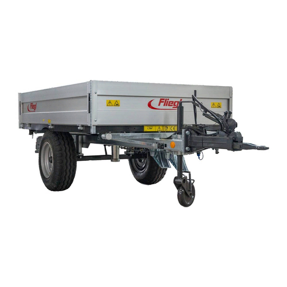
Fliegl EDK20 Operating Instructions Manual
Single-axle three-way tipper
Hide thumbs
1
2
3
4
Table Of Contents
5
6
7
8
9
10
11
12
13
14
15
16
17
18
19
20
21
22
23
24
25
26
27
28
29
30
31
32
33
34
35
36
37
38
39
40
41
42
43
44
45
46
47
48
49
50
51
52
53
54
55
56
57
58
59
60
61
62
63
64
65
66
67
68
69
70
71
72
73
74
75
76
page
of
76
Go
/
76
Contents
Table of Contents
Troubleshooting
Bookmarks
Table of Contents
Foreword
Table of Contents
Contents
Legal Notices
Identification
EC Declaration of Conformity
1 User Instructions
Purpose of this Document
Locations in the Operating Instructions
Illustrations Used
Cross References
Terminology: "Trailer", "Machine", "Vehicle
Figures
Scope of the Document
Presentation of Safety Instructions
Liability and Damages
Duty to Inform
2 Basic Safety Instructions
Designated Use
Reasonably Foreseeable Misuse
Service Life of the Machine
Risks When Working with the Machine
Residual Risks
Obligations of the Operator
Obligations of Personnel
Qualification of Operating Personnel
Qualification of Specialist Personnel
Personal Protective Equipment
Operational Safety
Operation Without Correct Start-Up
Safeguarding Perfect Technical Condition
Danger Due to Machine Damage
Technical Limits
Safety and Protective Devices
Emergency Stop Device
Description of Additional Safety and Protective Devices
Faulty Protective Devices
Inspecting Safety and Protective Devices
Workstation of Operating Personnel
Danger Areas
Safety Distance from Overhead Lines
Machine Identification
3 Description of the Machine
Applications
Design Variants - Standard
Functional Description
Layout of the Machine
Assemblies and Components
Technical Data - Standard Equipment
4 Transport and Installation
Basic Requirements
Supply and Installation
Drawbar Eye Connection
Establishing the Electrical Connection
Compressed Air Supply
Establishing Hydraulic Connections
5 Start-Up
First-Time Start-Up
Check before Start-Up
Returning to Service
6 Preparation and Setup
Draw Gear
Draw Gear with Top Hitch
Draw Gear with Overrun Brake
Overrun Brake Mechanism
Compressed Air Brake System with Manual Control Valve
Hydraulic Brake (Optional)
Hydraulic Brake Without Load Adjustment Valve
Hydraulic Brake with Load Adjustment Valve
Parking Brake
Hand Brake Lever - Overrun Brake
Farmer Stop - Parking Brake
Hand Brake Lever (Detachable Brake) - Parking Brake
Electrical Systems
7 Use and Operation
Trailer Operation
Before Operation
Setting up the Trailer Coupling on the Towing Vehicle
Coupling the Trailer
Conducting a Trial Run
Uncoupling the Trailer
Working with the Machine
General Safety and Operating Instructions
Loading the Trailer
Emptying the Trailer
Using the Side Panels
Tipping Linchpins
Tipping Processes
8 Basic Equipment (Standard, Optional)
Side Panel
Base Side Panel
Rear Panel (Base Side Panel ) with Grain Hatch
Flange Couplings
Side Panel Connectors
Supporting Mechanism
Underride Guard
Central Locking
Rear" Version
Side" Version
Mechanical Stopcock for Hydraulics (Maintenance Work)
9 Accessories
Marker Lights
Side Panel Tension Springs
Shunting Coupling
Side Panel Boom Chains with Storage Box
Removable Rear Exhaust Pipe with Outlet Spout
Removable Discharge Chute
Tarpaulin
Side Panel Support
Bracket for Folded Side Panel
Side Panel
First Attachment
Leaf Attachment
Tensioning Chain for Steel Side Panel
Hydraulic Line for 2Nd Trailer
Warning Markings, Side & Rear
Bridge Support for Maintenance Work
10 Service and Maintenance
Customer Service
Replacement Parts
Fliegl VIN (Vehicle ID Number) and Type Plate
Operational Maintenance
General Instructions for Maintenance
Cleaning the Vehicle
Corrosion Protection
Lubrication Schedule
Tyres and Wheels
Maintenance of the Brake System
Maintenance of the Compressed Air Brake System
Troubleshooting and Fault Elimination
List of Warning and Fault Signals
Decommissioning
Temporary Shutdown
Storage Conditions
Disassembly and Final Shutdown
Scrapping and Recycling
11 Standard Tipper Hydraulics
12 Electrics
Contact Assignment Plan - 12 V
Rear Light Versions
13 Axle Maintenance Work
14 Appendix
Volumetric Weights for Loosely Stacked Goods
Agricultural Products
Fertiliser
Construction Materials
Firewood
Conversion Table
15 Index
Advertisement
Quick Links
Download this manual
Translation of original operating instructions
EDK
Operating instructions
EDK single-axle three-way tipper
We are Fliegl.
GB
Table of
Contents
Previous
Page
Next
Page
1
2
3
4
5
Advertisement
Table of Contents
Need help?
Do you have a question about the EDK20 and is the answer not in the manual?
Ask a question
Questions and answers
Related Manuals for Fliegl EDK20
Farm Equipment Fliegl EDK25 Operating Instructions Manual
Single-axle three-way tipper (76 pages)
Farm Equipment Fliegl EDK40 Operating Instructions Manual
Single-axle three-way tipper (76 pages)
Farm Equipment Fliegl EDK50 Operating Instructions Manual
Single-axle three-way tipper (76 pages)
Farm Equipment Fliegl EDK60 Operating Instructions Manual
Single-axle three-way tipper (76 pages)
Farm Equipment Fliegl EDK80 Operating Instructions Manual
Single-axle three-way tipper (76 pages)
Farm Equipment Fliegl TDK 80 Operating Instructions Manual
(88 pages)
Farm Equipment Fliegl GARANT 90 Operating Instructions Manual
Drag hose spreader (76 pages)
Farm Equipment Fliegl GIGANT Operating Instructions Manual
Push-off trailer (128 pages)
Farm Equipment Fliegl ZDMK200 Operating Instructions Manual
(80 pages)
Farm Equipment Fliegl Noah TTW Operating Instructions Manual
Noah livestock trailer (68 pages)
Farm Equipment Fliegl ULW Operating Instructions Manual
(84 pages)
Farm Equipment Fliegl HFW 5000 Operating Instructions Manual
Turbo tank trailer (20 pages)
Farm Equipment Fliegl ULW 20 Operating Instructions Manual
Transfer trailer (84 pages)
Farm Equipment Fliegl GARANT 150 Operating Instructions Manual
Drag hose spreader (76 pages)
Farm Equipment Fliegl VARIO ULW 25 Operating Instructions Manual
Transfer trailer (84 pages)
This manual is also suitable for:
Edk25
Edk40
Edk50
Edk60
Edk65
Edk80
Table of Contents
Print
Rename the bookmark
Delete bookmark?
Delete from my manuals?
Login
Sign In
OR
Sign in with Facebook
Sign in with Google
Upload manual
Upload from disk
Upload from URL


Need help?
Do you have a question about the EDK20 and is the answer not in the manual?
Questions and answers