
Related Manuals for Fliegl TDK 80


Summary of Contents for Fliegl TDK 80
- Page 1 Translation of original operating instructions Operating instructions TDK tandem three-way tipper We are Fliegl.
- Page 2 Read these operating instructions prior to first-time start-up and observe them at all times! Retain for future reference!
-
Page 3: Foreword
Thank you for purchasing the Fliegl tandem three-way tipper. Fliegl machines and attachments are manufactured with care under continuous monitoring. The Fliegl tandem three-way tipper you have purchased is a product manufactured to the highest quality standards. To avoid accidents, and therefore personal injuries and material damage, you must read and understand the corresponding cautionary and warning notices in these operating instructions and on the Fliegl tandem three-way tipper before beginning operation or maintenance of the tandem three-way tipper. -
Page 5: Table Of Contents
Contents Contents Foreword ..............................2 Contents ..............................4 Legal notices ............................9 Identification ............................10 EC Declaration of Conformity ........................ 11 User instructions ..........................12 Purpose of this document ...................... 12 Locations in the operating instructions .................. 13 Illustrations used ........................13 Cross references ........................ - Page 6 Contents 2.13 Workstation of operating personnel ..................24 2.14 Danger areas ......................... 24 2.14.1 Safety distance from overhead lines ................25 2.15 Machine identification ......................25 Description of the machine......................27 Applications ........................... 27 Design variants – standard ....................27 Functional description ......................
- Page 7 Contents Use and operation .......................... 49 Trailer operation ........................49 7.1.1 Before operation ........................ 49 7.1.2 Setting up the trailer coupling on the towing vehicle ............49 7.1.3 Coupling the trailer ......................50 7.1.4 Conducting a trial run ......................51 7.1.5 Uncoupling the trailer ......................
- Page 8 Service and maintenance ......................67 10.1 Customer service ........................67 10.2 Replacement parts ........................ 67 10.3 Fliegl VIN (vehicle ID number) and type plate ............... 68 10.4 Operational maintenance ...................... 69 10.4.1 General instructions for maintenance ................69 10.4.2 Cleaning the vehicle ......................70 10.4.3...
- Page 9 Contents 15.1.1 Agricultural products ......................83 15.1.2 Fertiliser ........................... 83 15.1.3 Construction materials ..................... 83 15.1.4 Firewood .......................... 83 15.2 Conversion table ........................84 Index ............................85...
-
Page 10: Legal Notices
Mühldorf for the purpose of material examination to determine the damage. If a replacement is made, these parts become our property. 8. Legal warranty provisions also apply to the Fliegl tandem three-way tipper. -
Page 11: Identification
Copyright Fliegl, 2020. All rights reserved. Reproduction, in whole or in part, is only permitted with the approval of Fliegl. We are constantly developing and enhancing our products and therefore reserve the right to make changes to them without prior notification. -
Page 12: Ec Declaration Of Conformity
Product: Tandem three-way tipper Type TDK 80-88, TDK 80A-88 VR, TDK 110-88, TDK 140-88, TDK 160-88, TDK 200 Profi, TDK 255 Profi, TDK 80A-88 VR FOX, TDK 100 VR FOX, TDK 140 FOX, TDK 160 FOX, TDK 200 FOX Project designation:... -
Page 13: User Instructions
The regulations of agricultural employers' liability insurance associations also apply. Fliegl assumes no liability and honours no warranty for damage and malfunctions resulting from failure to comply with the operating instructions. -
Page 14: Locations In The Operating Instructions
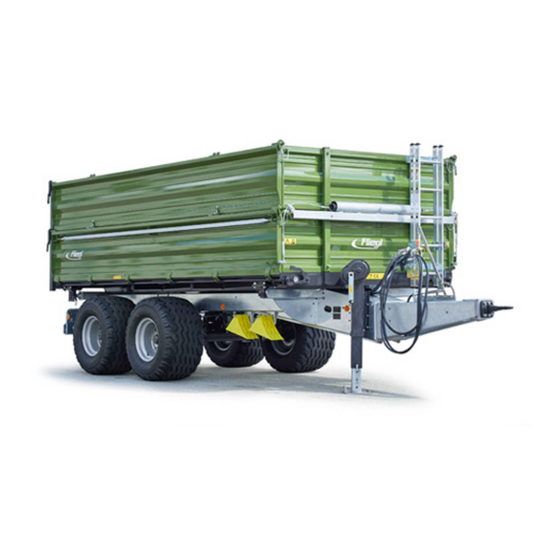
User instructions Locations in the operating instructions All directions and locations in these instructions are based on the operator's workstation. Left Rear Front Right Fig. 1 Locations in the documentation Rear Front Right side view Fig. 2 Main view of the tandem three-way tipper (model may vary) Illustrations used Instructions and system responses The steps to be taken by operating personnel are presented in the form of a (numbered) list. -
Page 15: Scope Of The Document
For your own safety, you should only use original replacement parts and accessory products. Fliegl Agrartechnik GmbH assumes no liability for the use of other products and any resulting damage. No claims for modification of delivered products can be made on the basis of the information, images and descriptions provided in this manual. -
Page 16: Basic Safety Instructions
Safety instructions 2. Basic safety instructions Failure to observe the safety instructions and warnings can pose a risk to persons, property and the environment. Non-compliance can also result in the loss of any claims for damage compensation on the part of the customer. When driving on public roads, be aware of the following: When driving on public roads, the provisions of the country-specific registration regulations must be observed. - Page 17 Safety instructions Notes on driving with the tandem three-way tipper The handling characteristics of a towing vehicle are influenced by the coupled trailer. Always adjust the vehicle speed to the local conditions. Avoid sudden cornering when driving uphill and downhill as well as when crossing a slope.
- Page 18 Safety instructions Handling the supporting mechanism Coupling the TDK Couple the TDK to the tractor (the coupling height can be adjusted via the supporting mechanism). The load on the supporting mechanism can be reduced by operating the actuation device.
-
Page 19: Designated Use
Operational safety of the machine is guaranteed only if it is used as intended. An unequally distributed load can cause damage to the vehicle, for which Fliegl Agrartechnik GmbH shall assume no liability. To be used exclusively for transporting agricultural and forestry products (e.g. -
Page 20: Reasonably Foreseeable Misuse
Attachment of additional equipment that has not been authorised or approved Use of non-original FLIEGL replacement parts Transportation of broken glass, scrap steel, sharp-edged goods, aggressive materials, artificial fertilizer, materials with a PH value higher than the neutral value... -
Page 21: Service Life Of The Machine
Safety instructions Service life of the machine The service life of this machine greatly depends on its correct use and maintenance as well as the specific applications and operating conditions. Following the instructions and information in these operating instructions will safeguard the operational readiness of the machine and maximise its service life. -
Page 22: Obligations Of Personnel
Safety instructions Obligations of personnel Before starting work, all personnel tasked with working on the machine undertake to: Comply with the basic regulations regarding work safety and accident prevention Read and comply with the safety section and warnings in these operating instructions Please contact the manufacturer with any questions;... -
Page 23: Personal Protective Equipment
Safety instructions 2.10 Personal protective equipment The operating company must provide the following personal protective equipment. Safety footwear with protective toe caps Define and provide personal protective equipment for the relevant application Only use personal protective equipment that is in flawless condition and offers effective protection ... -
Page 24: Technical Limits
Safety instructions 2.11.4 Technical limits If the technical limits of the machine are not maintained, this can lead to machine damage. This can result in accidents involving personal injury. Compliance with the following technical limits is particularly important from a safety perspective: ... -
Page 25: Workstation Of Operating Personnel
Safety instructions 2.13 Workstation of operating personnel The machine is designed to be used by one person only. The most important workstations are: The driver's seat of the towing vehicle (tractor) Fig. 3: Workstation on the machine 2.14 Danger areas Within the danger area of the machine, danger points exist that pose either a permanent hazard or are a potential source of unexpected risks. -
Page 26: Safety Distance From Overhead Lines
Safety instructions 2.14.1 Safety distance from overhead lines RISK OF DEATH! Always maintain the safety distances. Safety distance from the Overhead lines carrying voltage overhead line Up to 1 kV 1 m on all sides > 1 kV – 110 kV 3 m on all sides >... - Page 27 Safety instructions The following identifications are also located on the machine: CE identification number Indicates conformity with applicable EU directives related to the product, which also require a CE marking. (Located on type plate.) Type plate to specifically identify the machine Fig.
-
Page 28: Description Of The Machine
If possible, read it at the machine. That is the best way for you to familiarise yourself with the machine. Applications The machine is used to transport and spread goods as described in section 2.1 "Designated use". Design variants – standard Name Total weight TDK 80-88 8,000 kg (4,000 mm bridge) TDK 80A-88 VR 8,000 kg TDK 110-88... -
Page 29: Functional Description
Description of the machine Functional description Loading the machine Loading is performed as follows: After fully preparing or equipping the tandem three-way tipper Load the goods to be transported onto the loading bridge. Do not exceed the total maximum allowable weight for the TDK. Secure the goods. -
Page 30: Layout Of The Machine
Description of the machine Layout of the machine The following figure provides an overview of the most important components and assemblies and shows where they are installed on the machine: Fig. 6: Layout and components... -
Page 31: Assemblies And Components
Description of the machine Assemblies and components Item no. Title Draw gear Drawbar eye Compressed air connections Hydraulic connector Hose holder Supporting mechanism Lateral side panel lock Side central locking (right and left) Rear side panel lock Rear central locking Service, parking brake Axle assembly The different variations of these components are described under "Equipment"... - Page 32 Description of the machine Item 4 - hydraulic connectors Version 1: Tipper hydraulics A connector with a stopcock (for maintenance work) is provided for the tipper hydraulics. Version 2: Hydraulic brake A connection with a plug-in coupling is fitted for the hydraulic brake.
- Page 33 Description of the machine Item 10 - rear central locking When the central locking is operated, the rear base side panel folds open. Assembly – item 10 Fig. 16 Item 11 - service/parking brake With overrun brake unit: In the case of the overrun brake unit (service Overrun brake unit brake), the parking brake is combined with the overrun brake.
-
Page 34: Technical Data - Standard Equipment
Description of the machine Technical data – standard equipment Type: Body length 4,000 4,500 4,500 4,500 5,000 5,000 5,500 2,220 / 2,220 / 2,220 / 2,320 / 2,320 / Body width 2,220 2,420 2,170 2,170 2,170 2,220 2,220 Height of base side panel Length 1,500... -
Page 35: Transport And Installation
Transport and installation 4. Transport and installation Basic requirements The following means of transport are needed to transport the machine: Towing vehicles for agricultural or forestry applications (e.g. tractor) with suitable connections for towing couplings, brakes, hydraulics and lighting. The supply connections are located at the front in the hose tray. This information includes: Connections for the power supply Compressed air connections (type-specific) Hydraulic connector... -
Page 36: Supply And Installation
Transport and installation Supply and installation Note the permitted maximum speeds and axle loads with regard to the operational limits of the drawbar eye connection. These are specified on the type plate. 4.2.1 Drawbar eye connection The ordered flange coupling is fitted in top or bottom attachment position on the trailer. For possible drawbar eye types, refer to section 8.4. -
Page 37: Compressed Air Supply
Transport and installation 4.2.3 Compressed air supply Connection procedure: Connect the coupling head of the brake line (yellow) to the yellow port on the tractor as prescribed. Connect the coupling head of the supply line (red) to the red port on the tractor as prescribed. ... -
Page 38: Establishing Hydraulic Connections
Transport and installation 4.2.4 Establishing hydraulic connections A hydraulic oil supply and control by the towing vehicle are required for all work functions. Procedure: Clean the hydraulic connector and hydraulic socket if necessary. Connect the plug-in coupling, SVK coupling Fig. 24 Hydraulic connections size 3, to the correct SVK sleeve on the towing vehicle and check that it is correctly... -
Page 39: Start-Up
Start-up 5. Start-up First-time start-up Without a correct start-up in accordance with these operating instructions, the operational safety of the machine is not guaranteed. This can lead to accidents resulting in serious injury or death. All setting and adjusting tasks must be performed for first-time start-up. Before starting work, the operator must familiarise himself with all actuating devices and their function. -
Page 40: Preparation And Setup
Preparation and setup 6. Preparation and setup The following steps must be performed to set up and prepare the machine: Adjust the traction bar Establish the hydraulic and brake connections Establish the electrical connections Draw gear Three main variants: ... -
Page 41: Ball Head Coupling
Preparation and setup 6.1.4 Ball head coupling The ball head coupling must only be coupled with an approved coupling ball 80 (ball diameter 80 mm) that is suitable for ensuring safe attachment and locking. Fig. 25 Ball head coupling Maintaining the ball head coupling: Grease the contact surfaces at the coupling point. - Page 42 Preparation and setup Attention! The stopcocks on the steering axle must be opened before commencing travel to prevent damage to the hydraulic cylinders. When coupling the towing vehicle to the trailer, approaching in exactly the same position as when uncoupling will not work. The forced steering can therefore be re-coupled as follows. Procedure Approach the trailer with your towing vehicle as straight as possible.
-
Page 43: Setting Up The Forced Steering (Optional)
Preparation and setup Setting up the forced steering (optional) Adjusting and venting the forced steering (working operation). The forced steering is pre-fitted to the trailer and must be adapted to the relevant towing vehicle by the user (see also section 6.1.5). Prerequisites Hitch the trailer to the towing vehicle (tractor) via the flange coupling. - Page 44 Preparation and setup Fig. 30 Tandem steering axle L1 = steering axle stopcock L2 = steering axle stopcock The two stopcocks (L1, L2) on the steering axle must be opened during driving operation. Attention! The trailer is delivered with the stopcocks closed. Stopcocks L1 and L2 must be opened before commencing travel to prevent damage to the hydraulic cylinders.
-
Page 45: Overrun Brake Mechanism
Preparation and setup Overrun brake mechanism This option is only available when using the trailer in Germany. The brake linings must first adjust to the brake drum, which will result in differing temperatures. This can create some play in the brakes. The overrun brake must then be adjusted. -
Page 46: Compressed Air Brake System With Alb, Brake Force Regulator (Optional)
Preparation and setup Compressed air brake system with ALB, brake force regulator (optional) Check the braking effect of the compressed air brake system before setting off. For every use (driving operation), the brake force must be set according to the trailer load. -
Page 47: Hydraulic Brake (Optional)
Preparation and setup Hydraulic brake (optional) This option is not available when using the trailer in Germany. Check the braking effect of the hydraulic brake before setting off. 6.5.1 Hydraulic brake system without load adjustment valve The trailer can be equipped with an optional hydraulic brake system. The brake line is connected to the hydraulic brake connection of the towing vehicle. -
Page 48: Parking Brake
Preparation and setup Parking brake If the trailer is not equipped with a parking brake, the wheel chocks must be used to prevent the trailer from rolling away. Farmer stop – parking brake 6.6.1 Applying the brake: To activate the parking brake, pull the actuating lever towards the drawbar eye. -
Page 49: Hand Brake Lever (Detachable Brake) - Parking Brake
Preparation and setup Hand brake lever (detachable brake) – parking brake 6.6.3 Prerequisite: If there is no retaining bracket on your towing vehicle, you must fit a suitable bracket at an appropriate location. It should be easy to reach while working. Positioning of bracket ... -
Page 50: Use And Operation
Use and operation 7. Use and operation Read carefully. If there is anything you do not understand, please contact the manufacturer to exclude the possibility of operating errors. Trailer operation When coupling the tandem three-way tipper, there is a risk of crushing between the trailer and the towing vehicle. -
Page 51: Coupling The Trailer
Use and operation 7.1.3 Coupling the trailer Always follow the instructions in section 4.2 for the coupling and uncoupling process and read through this section carefully before first-time start-up. Move the towing device of the towing vehicle or the drawbar eye of the trailer to the correct height. -
Page 52: Conducting A Trial Run
Use and operation 7.1.4 Conducting a trial run After the machine is set up and prepared and before work begins, a trial run must be conducted in unloaded condition. Objective Check to ensure the machine is set up correctly and functioning properly. Prerequisites Machine is ready for operation Machine is fully set up... -
Page 53: Working With The Machine
Use and operation Working with the machine 7.2.1 General safety and operating instructions The following section contains some general notes on safety and operation for working with the tandem three-way tipper, repeated and summarized together for better clarity: The weights and loads specified on the type plate must be observed. Note the maximum permitted drawbar load of the trailer coupling. -
Page 54: Loading The Trailer
Use and operation 7.2.2 Loading the trailer Carrying persons on the trailer is prohibited, as is standing on the trailer in general. When transporting bulk materials with a high volume weight, there is a risk of overloading and damaging the trailer. Observe the permitted total weight of the trailer. -
Page 55: Using The Side Panels
Use and operation 7.2.4 Using the side panels Folding down the side panels The side panels can be folded down from the side and rear. Tandem three-way tippers are fitted with swing-mounted side panels. To open the lower side panel, you must first remove the connection bolts between the side panels and attached panels. -
Page 56: Tipping Linchpins
Use and operation 7.2.5 Tipping linchpins The tandem three-way tipper is equipped with two tipping linchpins, which prevent accidental diagonal insertion. Rear tip bearing The tipping linchpins must be inserted in the side of Guide plate the tipper before the tipping operation. Accidentally inserting the bolts diagonally is prevented with correct guide plates. -
Page 57: Basic Equipment (Standard, Optional)
Equipment 8. Basic equipment (standard, optional) Side panel 8.1.1 Base side panel The base side panel of the tipper (different heights of the base side panels): Fig. 42 Base side panel 8.1.2 First and second attachment The attachment in combination with the base side panel First attachment ... -
Page 58: Gravel Flap Version
Equipment 8.2.2 Gravel flap version The TDK can be equipped with a hydraulic gravel flap, which protects the rear of the vehicle and the rear lights against damage. Fig. 45 Gravel flap Caution: Loose bulk material flows out immediately without tipping. Supporting mechanism Depending on the TDK version, the following types of supporting mechanism are available. -
Page 59: Underride Guard
Equipment Underride guard In the case of a collision, the other vehicle can drive or slide underneath the trailer even at low speeds. The underride guard offers resistance for the energy- absorbing parts of the colliding vehicle's body (known as crumple zones), thus allowing the energy generated by the collision to be dissipated. -
Page 60: Side" Version
Equipment 8.6.2 "Side" version Operation Pressing the handle in the direction of rotation opens the lower side central locking. Only the lower side panel folds out to the side; the first attachment remains in its locked position. Fig. 49 Central locking Be aware of the internal load pressure. -
Page 61: Mechanical Stopcock For Hydraulics (Maintenance Work)
Equipment Mechanical stopcock for hydraulics (maintenance work) Failure to observe the above instructions can result in life-threatening injuries. The stopcock is integrated in the supply line to the tipper press. It is used to block the hydraulics during maintenance work. Open Closed Fig. -
Page 62: Accessories
Equipment 9. Accessories Reversing/monitoring camera A reversing camera is recommended to improve visibility when reversing. The monitoring camera allows you to observe the loading and unloading process and can also be connected to the reversing camera. Fig. 51 Camera system (No separate monitor needed.) Marker lights Marker light types... -
Page 63: Shunting Coupling
Equipment Shunting coupling The mechanical version is available as a coupling mechanism for hitching a second trailer. The mechanical coupling must be opened and closed manually. Fig. 55 Mechanical coupling This version is not authorised for use on public roads. Automatic trailer coupling The automatic version is available as a coupling mechanism for hitching a second trailer. -
Page 64: Removable Rear Exhaust Pipe With Outlet Spout
Equipment Removable rear exhaust pipe with outlet spout The outlet amount can be set manually via a built-in gate valve. Open in direction of arrow Fig. 58 Pipe outlet Removable discharge chute Discharge chutes supplement your standard grain hatch and facilitate the emptying of bulk materials. -
Page 65: Roll-Off Tarpaulin With Operating Platform
Equipment 9.13 Roll-off tarpaulin with operating platform Operation Untie the tarpaulin on the front, side and rear panels. Stand on the operating platform. Rotate the crank handle to the left to fully open the tarpaulin up to the end stop. Use the tie-downs to secure the tarpaulin again when driving. -
Page 66: Hydraulic Rear Panel (Optional)
Equipment 9.15 Hydraulic rear panel (optional) One hydraulic connection: The hydraulics of the trailer are configured such that, while loaded, the rear panel opens first after which the tipper bridge tilts up. In addition, there are two stopcocks at the front of the drawbar, which can be used to lock the rear panel and the tipping cylinder. -
Page 67: Bridge Support For Maintenance Work
Equipment 9.17 Bridge support for maintenance work Attention! Before performing maintenance work between the tipper bridge and the chassis, the stopcock for the tipper hydraulics must be closed. This prevents accidental lowering of the tipper bridge. Failure to observe the above instructions can result in life-threatening injuries. -
Page 68: Service And Maintenance
Regular maintenance in accordance with the maintenance plan is essential to the efficient use of the machine. 10.1 Customer service Please contact: Fliegl Agrartechnik GmbH Service Department Bürgermeister-Boch-Straße 1 84453 Mühldorf am Inn, Germany Telephone: +49 (0)8631 / 307 - 461... -
Page 69: Fliegl Vin (Vehicle Id Number) And Type Plate
Service and maintenance 10.3 Fliegl VIN (vehicle ID number) and type plate Vehicle manufacturer Vehicle class EU type approval number Vehicle ID number (VIN) Total weight (axle load) Drawbar load Axle load of 1st axle Axle load of 2nd axle... -
Page 70: Operational Maintenance
Service and maintenance 10.4 Operational maintenance 10.4.1 General instructions for maintenance Operational maintenance helps to ensure trouble-free and efficient use of the machine. Operating personnel can perform this work after receiving appropriate instruction. Maintenance task Interval Chassis Check tyre pressures Check wheel nuts to ensure correct tightening torque Lateral play of wheel hub bearing Drain the water from the compressed air reservoir... -
Page 71: Cleaning The Vehicle
Service and maintenance Frame: Check the suspension, axle mountings and screw connections every day and re-tighten if necessary. If technical changes are found in the springs or too much play on the bearing bolts, rectify the problem immediately. Check the mounting bolts on the drawbar eye after the first 10 operating hours, then check every 50 operating hours to ensure they are firmly seated and re-tighten if necessary. -
Page 72: Corrosion Protection
10.4.4 Lubrication schedule The lubrication schedule applies to all Fliegl tandem three-way tippers. Failure to ensure correct and sufficient lubrication carries a risk of costly repairs at a later stage. Dispose of old oil and grease in the correct manner. -
Page 73: Tyres And Wheels
Service and maintenance 10.4.5 Tyres and wheels Check and adjust the tyre pressure every 3 months on cold tyres based on the following table: 11.5/80-15.3 10 PR 3.40 12.5/80-18 14 PR 4.30 15.0/55-17 10 PR 3.60 15/70-18 16 PR 4.25 19.0/45-17 14 PR 3.90... - Page 74 Service and maintenance Typical hazards when working with tyres and wheels: Incorrect tyre filling pressure Road damage Lack of maintenance Excessive load or high speed The service life of tyres depends on many different factors and therefore cannot be predicted with sufficient accuracy. Physical effects: Wear Damage...
-
Page 75: Maintenance Of The Brake System
Service and maintenance 10.5 Maintenance of the brake system Adjustments and repairs to the brake system must only be performed by specialist workshops or professional brake repair services. Have the brake system checked thoroughly on a regular basis. Always stop the tractor immediately in the case of any brake system malfunctions. Have any malfunctions rectified immediately. - Page 76 Service and maintenance Brake cylinder Check the brake cylinder. Only up to 2/3 of the brake cylinder stroke should be used. If this is exceeded, the brake system must be re-adjusted or repaired by a specialist brake workshop. Mechanical ALB control ALB = automatic load-dependent brake force regulation.
-
Page 77: Troubleshooting And Fault Elimination
Service and maintenance 10.6 Troubleshooting and fault elimination Special caution when rectifying faults. Consult trained service personnel or visit a specialist workshop. If necessary, contact the manufacturer's customer service department. 10.6.1 List of warning and fault signals Fault / error message Possible cause(s) Remedy Compressed air brake with... - Page 78 Service and maintenance Fault / error message Possible cause(s) Remedy Hydraulics move too slowly Insufficient oil in the hydraulic Check the oil level and top up if or not at all system necessary Hydraulic coupling connected Check the connections incorrectly Hydraulic coupling faulty Check the coupling and replace if necessary...
-
Page 79: Decommissioning
Clean the entire trailer thoroughly inside and out, then leave the trailer to dry. Spray the entire trailer inside and out with a film of oil. Store the Fliegl trailer in a dry, clean and rust-free place. We recommend covering the trailer with a tarpaulin to protect it against dust etc. -
Page 80: Standard Tipper Hydraulics
Hydraulics 11. Standard tipper hydraulics Cut-off valve Tipper cylinder Stopcock (optional) SVK connector with protective cap Hose clamp Fig. 71: Hydraulic plan – working hydraulics DETAIL A ... -
Page 81: Brake System
Brake 12. Brake system SUPPLY BRAKE Fig. 73: Compressed air diagram with mech. ALB (Please request other compressed air diagrams separately. Hydr. brake (export only)) HALDEX BRAKE PRODUCTS Dual line brake system according 380 090 300 GmbH to StVZO/lof Customer: 11/07/2003 Veh. -
Page 82: Electrics
Electrics 13. Electrics 13.1 Contact assignment plan According to DIN/ISO 1724 (12 V) Item 1 L yellow; left indicator Item 7 58L black; left rear light Item 6 54 red; brake light Item 2 54G blue; rear fog light Item 5 58R brown; right rear light Item 4 R green;... -
Page 83: Axles
Axles 14. Axles 14.1 Axle assemblies 14.1.1 Gigant tandem assembly Fig. 75 Gigant assembly 14.1.2 Gigant Plus tandem assembly Fig. 76 Gigant Plus assembly 14.1.3 Titan tandem assembly Fig. 77 Titan assembly 14.2 Axle maintenance work For information on the required maintenance work for the relevant axles, please contact the manufacturer of the installed axles. -
Page 84: Appendix
Appendix 15. Appendix 15.1 Volumetric weights for loosely stacked goods 15.1.1 Agricultural products 1 m³ kg (approx.) 1 m³ kg (approx.) Peas 780 - 820 Beet leafs and tops 350 - 370 Fodder beets 325 - 700 Straw (wire-bound high-density bales) Approx. -
Page 85: Conversion Table
Appendix 15.2 Conversion table The following table facilitates the conversion of specific units SI units (metric) Imperial units Size Factor Unit name Abbreviation Unit name Abbreviation Area Hectare 2.47105 Acre acres Litres per l/min 0.2642 Volume flow minute US gallons rate per minute Cubic metres... -
Page 86: Index
Index 16. Index ALB regulator ..............75 Obligations of personnel ..........21 Applications ..............27 Obligations of the operator ..........20 Assemblies and components .......... 30 Operation ................ 49 Basic safety instructions ..........15 Personal protective equipment ........22 Preparation and setup ............ 39 Cleaning ................ - Page 88 Fliegl Agrartechnik GmbH Bürgermeister-Boch-Str. 1 D-84453 Mühldorf a. Inn Tel.: +49 (0) 86 31 307-0 Fax: +49 (0) 86 31 307-550 e-Mail: info@fliegl.com 1-009B06203.1...
Need help?
Do you have a question about the TDK 80 and is the answer not in the manual?
Questions and answers