Advertisement
Quick Links
• RELÉ DIFERENCIAL DE FALLOS A TIERRA
• EARTH FAULT DIFFERENTIAL RELAY
9
8
7
6
5
4
3
2
1
El relé supervisa permanentemente el circuito toroidal-relé, si este se
*
interrumpe el relé dispara y enciende de forma intermitente el LED rojo.
El equipo dispone de doble circuito de medida lo que le confiere una
**
seguridad redundante. Si uno de estos circuitos se averiase el relé
seguiría midiendo correctamente por el otro. Esta situación es detectada
por la función auto-diagnostico de que dispone y señalizada mediante el
parpadeo del LED verde ON. Cuando se de esta improbable situación es
aconsejable sustituir el relé cuando sea posible.
A
INSTRUCCIONES DE SEGURIDAD
• Para evitar descargas eléctricas durante la instalación o manipulación del
relé, asegúrese de que no hay tensión en la línea ni tensión auxiliar.
• Comprobar que la tensión nominal es la correcta.
B
ESQUEMA DE CONEXIONES
• Cableado: Los esquemas se representan con el relé sin tensión de
alimentación conectada.
• Conectar el dispositivo de disparo (bobina de emisión, bobina de mínima,
contactor, etc.) según el siguiente cuadro.
tierra
L1
L2 L3 N
earth
Fig. 1
Prioridad de seguridad
Prioridad de servicio
10 1 1 12 13
Dimensiones / Dimensions
72,6
22,4
100
C
A1
A2
U
= 0
s
U
= 0
s
D30
Normal
Normal
1
2
Disparado
Disparado
Tripped
Tripped
1
2
CT-1
14 12 10
Bobina de mínima
C
Contactor
Fig. 2
Fig. 1
Undervoltage trip coil
C
Contactor
1
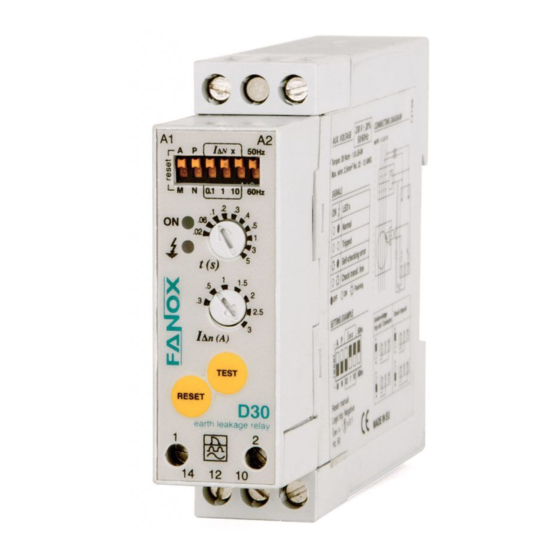
Contactos de salida
Bornas conexión transformador
2
toroidal CT-1
3
Botón de rearme
4
Botón de prueba
5
Ajuste sensibilidad
6
Ajuste del tiempo de retardo
7
LED rojo
8
LED verde
9
Alimentación
10
Tipo de rearme
11
Selección lógica de disparo
12
Factor multiplicador de sensibilidad
13
Selección frecuencia de la red
The relay constantly supervises the toroidal circuit-relay. Should this
*
become interrupted the relay trips and the red LED begins to flash.
The unit is equipped with a double measuring circuit providing
**
redundant safety. Should one of these circuits fail, the relay shall continue
measuring correctly via the other one. This situation is detected by its
self-diagnosis function and is signalled by means of the flashing green
LED ON. Should this improbable situation occur it is advisable to replace
the relay as soon as possible.
• To prevent electric discharges during the installation or handling of the
relay, ensure there is no voltage in the line and no auxiliary voltage.
• Check that the nominal voltage is correct.
• Wiring: The schematics show the relay with supply voltage disconnected.
• Connect the trip device (shunt trip coil, undervoltage trip coil, contactor,
etc.) according to the following table.
tierra
L1
L2 L3 N
earth
Lógica disparo / Logic trip
Lógica disparo / Logic trip
Pos.
Neg.
Pos.
Neg.
10
10
10
10
14
14
14
14
12
12
12
12
10
10
10
10
14
14
14
14
12
12
12
12
10
10
10
10
14
14
14
14
12
12
12
12
C
Bobina de emisión
Lógica de disparo
Fig. 1
Posit.
Fig. 2
Negat.
C
Shunt trip coil
Logic trip
Output contacts
Connection terminals for toroidal
transformer CT-1
Reset push-button
Test push-button
I
∆n
Sensitivity adjustment
Delay time adjustment
Red LED
Green LED
Supply
Reset type
Logic trip selection
Sensitivity multiplier factor
Network frequency selection
SAFETY INSTRUCTIONS
CONNECTION DIAGRAM
C
A1
A2
Fig. 2
D30
1
2
1
2
CT-1
14 12 10
P
Safety priority
Service priority
N
D30
I
∆n
A
B
Advertisement

Related Manuals for FANOX D30


Summary of Contents for FANOX D30
- Page 1 • RELÉ DIFERENCIAL DE FALLOS A TIERRA • EARTH FAULT DIFFERENTIAL RELAY Contactos de salida Output contacts Bornas conexión transformador Connection terminals for toroidal toroidal CT-1 transformer CT-1 Botón de rearme Reset push-button Botón de prueba Test push-button 10 1 1 12 13 Ajuste sensibilidad ∆n Sensitivity adjustment...
- Page 2 Standards EN 60947-2-B,EN 50263,EN61543 (A11), IEC60255-5, VDE 0664 PAE Asuaran Edif. Artxanda, 23 • 48950 ERANDIO • BIZKAIA • ESPAÑA FANOX se reserva el derecho Tel. +34 94 471 14 09 • Fax +34 94 471 05 92 efectuar cualquier modificación...
Need help?
Do you have a question about the D30 and is the answer not in the manual?
Questions and answers