Table of Contents
Advertisement
Advertisement
Table of Contents

Related Manuals for Price Antec controls CAVA


Summary of Contents for Price Antec controls CAVA
- Page 1 CAVA Touchscreen Fume Hood Controller MANUAL v100...
-
Page 2: Table Of Contents
CAVA - MANUAL TABLE OF CONTENTS TABLE OF CONTENTS ..................................I INTRODUCTION ....................................1 General ......................................1 Product Overview ..................................1 Features ......................................1 Installation & Service ..................................1 Technical Specifications ................................1 Sash, Sidewall & Hybrid Configuration ............................2 MECHANICAL INSTALLATION.................................3 Mounting Options ..................................3 ELECTRICAL INSTALLATION ................................4 Wiring ......................................4 Room Information Network (RIN) ..............................5 Controller Area Network (CANbus) ...............................6... -
Page 3: Introduction
CAVA - MANUAL INTRODUCTION General Installation & Service In this manual, you will find: A qualified person must perform installation and electrical wiring in accordance with all • Cava™ technical specifications applicable codes and standards, including • Cava™ mechanical and electrical installation fire-rated construction practices. -
Page 4: Technical Specifications
CAVA - MANUAL Technical Specifications Environmental 32°F to 130°F (0°C to 55°C), 5% to 95% R.H. (Non-Condensing) (Operating) Environmental -22°F to 158°F (-30°C to 70°C), 0% to 95% R.H. (Non-Condensing) (Storage) 24 VAC ±10%, 50/60 Hz, 12 VA Max (excluding external loads), Class 2 Input Power Binary Input (Contact Closure or Active) 4 Universal Inputs (Includes sidewall... -
Page 5: Sash, Sidewall & Hybrid Configuration
CAVA - MANUAL Sash, Sidewall & Hybrid Configuration Control Settings No Control – Monitor Only This method disables all control. The device will only monitor the face velocity of the fume hood / cabinet using a Sash Position Sensor and/or a Sidewall Velocity Sensor, but will not change its airflow or face velocity. -
Page 6: Mechanical Installation
CAVA - MANUAL MECHANICAL INSTALLATION It is recommended to mount Cava™ at approximately 5½’ to 6’ from the floor. This will allow the interface to be at an appropriate height for use during setup and during normal operation. Mounting Options Cava™... -
Page 7: Electrical Installation
CAVA - MANUAL ELECTRICAL INSTALLATION Wiring NOTES: For Typical Network Wiring Diagrams, see Room Information Network (RIN), Controller Area Network (CAN), and BACnet MS/TP Network sections. All wire connections to the Cava™ screw connection terminals must be between 16-26 AWG wire. Current and voltage drop should be taken into consideration when selecting wire gauge. -
Page 8: Room Information Network (Rin)
CAVA - MANUAL Room Information Network (RIN) Physical Connection RIN consists of a 4-wire network architecture (RX-, RX+, What is the Room Information Network? TX-, TX+) using a daisy-chain connection between each The Antec Controls Pace™ and Cava™ operate on a device on the network segment. -
Page 9: Controller Area Network (Canbus)
CAVA - MANUAL Controller Area Network (CANbus) Physical Connection CANbus consists of a 3-wire network architecture. Daisy What is the Controller Area Network? chain the CANH, CANL, and COM connections of all The Controller Area Network (CANbus) is a communication devices on the network as shown below. -
Page 10: Bacnet Ms/Tp Network
CAVA - MANUAL BACnet MS/TP Network BACnet Points See Cava™ Product Submittal at AntecControls.com NOTE: BACnet is only used on Cava™ when it does not BACnet Points List. have a RIN connection to a Pace™ controller in the room. What is BACnet? Physical Connection BACnet consists of a 3-wire network architecture. -
Page 11: Network Architecture Summary
CAVA - MANUAL Network Architecture Summary See the information outlined in the example below for a summary of the network architecture of Cava™. Typical Laboratory Wiring Line Color Network Type Considerations Blue Room Information Network (RIN) Up to 24 controllers (PACE and CAVA combined), with a maximum of 16 CAVAs Daisy chained network wiring between each device on the network NOTE: A connection through a RIN access point is used to start-up and commission the... -
Page 12: Fume Hood Accessories
CAVA - MANUAL FUME HOOD ACCESSORIES Cava™ can take advantage and multiple fume hood accessories to CAUTION effectively monitor and control fume hood face velocity, reduce energy consumption, and keep work environments safe. Different types of fume hood accessories can be used with Cava™. When using Fume hood accessories provided by Antec Controls include: accessories by Others, ensure that the Fume Hood Valve Module (FVM) - Venturi Valve (VV) Applications... - Page 13 CAVA - MANUAL Electrical Installation CAUTION POT1 and POT2 terminations Wire Color Terminal Green Black Indicator Color Description Solid Green Device is functioning properly Blinking Green Used for ping identification Solid Magenta Incompatible firmware NOTES: For Typical CAN Wiring Diagrams, see Controller Area Network (CAN) section.
-
Page 14: Fume Hood Valve Module (Fvm) - Venturi Fx Valve (Vfx) And Terminal Unit (Tu) Applications
CAVA - MANUAL Fume Hood Valve Module (FVM) - Venturi FX Valve (VFX) and Terminal Unit (TU) Applications The Fume Hood Valve Module (FVM) works directly with Cava™ to accurately meet the required exhaust airflow and fume hood face velocity. The FVM used in Venturi FX Valve (VFX) and Terminal Unit (TU) applications uses high-accuracy pressure readings to measure the airflow through the valve. - Page 15 CAVA - MANUAL Electrical Installation Indicator Color Description Solid Green Device is functioning properly Blinking Green Used for ping identification Solid Magenta Incompatible firmware NOTES: For Typical CAN Wiring Diagrams, see Controller Area Network (CAN) section. All wire connections to the FVM screw connection terminals must be between 16-26 AWG wire. Current and voltage drop should be taken into consideration when selecting wire gauge.
-
Page 16: Sash Position Sensor (Sps)
CAVA - MANUAL Sash Position Sensor (SPS) The Sash Position Sensor (SPS) reports the open area of the fume hood by measuring the sash location. Cava™ uses the SPS measurement to adjust the exhaust airflow based upon the measured sash opening. The SPS contains a long- life potentiometer (over 250,000 cycles) and is constructed using a stainless-steel cable for stability and a thick plastic cover for protection against airborne chemical agents. - Page 17 CAVA - MANUAL Option C Mount the SPS on the top of the fume hood. STEP 1 Ensure the cable is free from obstruction along the entire length of sash movement. STEP 2 The sensor cable may be attached directly to the counterweight. This configuration may be desired when the sash connects to the counterweight with a belt and pulley system.
-
Page 18: Sidewall Velocity Sensor (Svs)
CAVA - MANUAL Sidewall Velocity Sensor (SVS) The Sidewall Velocity Sensor (SVS) reports face velocity to Cava™ by measuring the differential pressure between the fume hood and the laboratory. Cava™ uses the SVS measurement to adjust the exhaust to meet the required face velocity. The SVS consists of multiple components: •... - Page 19 CAVA - MANUAL CAUTION Mounting position is critical to ensure the accuracy of the SVS. Ensure that there are no sharp bends or kinks in the tubing during the installation. Improper installation will cause failure of the SVS. Regardless of where the SVS is mounted, the following steps outline how to install the SVS components. STEP 1 With the sash in the fully open position, drill a 5/16”...
- Page 20 CAVA - MANUAL Electrical Installation Indicator Color Description Solid Green Device is functioning properly Blinking Green Used for ping identification Solid Magenta Incompatible firmware NOTES: For Typical CAN Wiring Diagrams, see Controller Area Network (CAN) section. All wire connections to the SVS screw connection terminals must be between 16-26 AWG wire. Current and voltage drop should be taken into consideration when selecting wire gauge.
-
Page 21: Fume Hood Presence Sensor (Fps)
CAVA - MANUAL Fume Hood Presence Sensor (FPS) The Fume Hood Presence Sensor (FPS) detects user movement in the vicinity of the fume hood and sends a signal to Cava™. Based on the signal, Cava™ responds by adjusting to a configurable fume hood mode. The FPS boasts a low profile and allows for an adjustable coverage pattern. -
Page 22: Interface
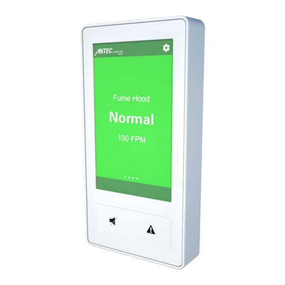
CAVA - MANUAL INTERFACE Home Screen The Cava™ Home Screen will be displayed on the interface once setup has been completed through Antec Toolbox. The Home Screen provides the user with a clear indication of the fume hood status and face velocity reading. Home Screen Components Display Component Description... -
Page 23: Configurable Fume Hood Modes
CAVA - MANUAL Configurable Fume Hood Modes Cava™ comes with four fully configurable fume hood modes. These modes can be configured and updated through Antec Toolbox by using the RIN Ethernet Port on the back of the device. The fume hood modes will be configured during system start-up by your local certified start-up technician. Refer to your NOTE: start-up technician for changes to your fume hood modes. -
Page 24: Settings
CAVA - MANUAL Settings The settings are accessible through the Home Screen and are password protected (see Home Screen section). Settings Menu Menu Item Available Options Description Mode Override No Override Used to override current CAVA mode and enter [Room Mode #1] any other mode. -
Page 25: Maintenance
CAVA - MANUAL MAINTENANCE Troubleshooting Symptom Solution Check the power connection to CAVA. CAVA is non-responsive Ensure CAVA has 24VAC power with a voltmeter. Cycle power to CAVA. Ensure CAVA has 24VAC power. Ensure the Binary Output has been configured to the appropriate usage. Binary Output not functioning CAVA provides a low side binary output. -
Page 26: Replacement Parts
CAVA - MANUAL Replacement Parts Replacement parts are available. Please contact your local Antec Controls Representative. Technical Support If technical support is required, please contact us: By Email: FieldSupport@AntecControls.com By Phone: 866.884.3524 Hours of Operation: Monday – Friday, 8am to 4:30pm CT NOTE: If you will need support after hours, please contact us 48 hours in advance. -
Page 27: Cava™ Jigsaw Cut-Out
CAVA - MANUAL APPENDIX A Cava™ Jigsaw Cut-Out Cava™ Circular Cut-Out Fume Hood Presence Sensor 24 | CAVA – Manual | AntecControls.com... - Page 28 Limited Warranty. The complete product catalog can be viewed online at AntecControls.com ® Antec Controls by Price is a registered trademark of Price Industries Limited. © 2021. Printed in Canada. v100...
Need help?
Do you have a question about the Antec controls CAVA and is the answer not in the manual?
Questions and answers