
Subscribe to Our Youtube Channel
Related Manuals for Lanner NCA-5310


Summary of Contents for Lanner NCA-5310
- Page 1 NCA-5310 User Manual Industrial Embedded Platforms NCA-5310 User Manual Version: 1.2 Date of Release:2021-08-26...
- Page 2 - assumed to be qualified in the servicing of computer equipment, such as professional system integrators, or service personnel and technicians. The latest version of this document can be found on Lanner’s official website, available either through the product page or through the Lanner Download Center page with a login account and password.
- Page 3 Phone support is offered to our customers in the United States and Canada. Toll-free customer service number: +1 855-852-6637 This document is copyrighted © 2021 by Lanner Electronics Inc. All rights are reserved. The original manufacturer reserves the right to make improvements to the products described in this manual at any time without notice.
- Page 4 NCA-5310 User Manual Taiwan Corporate Headquarters China Lanner Electronics Inc. Beijing L&S Lancom Platform Tech. Co., Ltd. 7F, No.173, Sec.2, Datong Rd. Xizhi District, Guodong LOFT 9 Layer No. 9 Huinan Road, New Taipei City 22184, Taiwan Huilongguan Town, Changping District, 立端科技股份有限公司...
- Page 5 NCA-5310 User Manual Intel® and Intel® Celeron® are trademarks of Intel Corporation or its subsidiaries in the U.S. and/or other countries. Microsoft Windows and MS-DOS are registered trademarks of Microsoft Corp. All other product names or trademarks are properties of their respective owners.
- Page 6 NCA-5310 User Manual Follow these guidelines to ensure general safety: Keep the chassis area clear and dust-free during and after installation. Do not wear loose clothing or jewelry that could get caught in the chassis. Fasten your tie or scarf and roll up your sleeves.
- Page 7 The installation of this product must be performed by trained specialists; otherwise, a non-specialist might create the risk of the system’s falling to the ground or other damages. Lanner Electronics Inc. shall not be held liable for any losses resulting from insufficient strength for supporting the system or use of inappropriate installation components.
- Page 8 NCA-5310 User Manual Reliable Grounding - Reliable grounding of rack mounted equipment should be maintained. Particular attention should be given to supply connections other than direct connections to the branch circuit (e.g. use of power strips). Warning Class I Equipment. This equipment must be earthed. The power plug must be connected to a properly wired earth ground socket outlet.
- Page 9 The product is intended to be supplied UL listed DC power source with rated -48V to -60 Vdc, 22A minimum. Maximum operating ambient is 40° C minimum and the altitude of operation = 5000m minimum. The power cable should use 12 AWG minimum. If further assistance is required, please contact Lanner Technical Support.
- Page 10 NCA-5310 User Manual Main Features ..........................12 Package Content ..........................12 Optional Accessories ........................12 Ordering Information ........................12 System Specifications ........................13 Front Panel ............................. 14 Rear Panel ............................15 Motherboard Information ......................16 Opening the Chassis ........................24 Installing the CPU ...........................
- Page 11 NCA-5310 User Manual Security ............................67 Save and Exit Menu ........................71 AMD CBS ............................73 AMD PBS Option ..........................82 Event Logs ............................83...
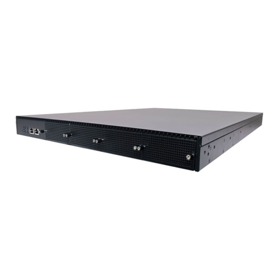
- Page 12 NCA-5310 User Manual The NCA-5310 series unit is a high performance 1U Rack mount network security system utilizing the cutting- edge capabilities of the AMD Rome/Naples platform with one EPYC 7000 Series CPU. AMD EPYC 7000 Series w/ Support for Naples (up to 32C64T) & Rome (up to 64C128T) 8x 288-pin DIMM, Max.
- Page 13 NCA-5310 User Manual 1U 19” Rackmount Form Factor AMD EPYC 7000 Series w/ Support for Naples (up to 32C64T) & Processor Options Rome (up to 64C128T) CPU Socket Platform Chipset Security Acceleration 40Gbps Encryption + 40Gbps Decryption BIOS AMI SPI Flash BIOS...
- Page 14 NCA-5310 User Manual Description Reset button For software reset System Power LED Indicators System Status HDD Activity USB Ports 2x USB 3.0 RJ45 Port 1x RJ45 port Console Port 1x Console port NIC Module Slot 4x NIC Slots...
- Page 15 NCA-5310 User Manual Description Power Supply 2 x 800W Redundant PSU Fans 5 x Hot-swappable Cooling Fans Power Switch 1 x Power Button...
- Page 16 NCA-5310 User Manual The block diagram indicates how data flows among components on the motherboard. Please refer to the following figure for your motherboard’s layout design.
- Page 17 NCA-5310 User Manual The motherboard layout shows the connectors and jumpers on the board. Refer to the following picture as a reference of the pin assignments and the internal connectors.
- Page 18 NCA-5310 User Manual The pin headers on the motherboard are often associated with important functions. With the shunt (Jumper) pushed down on the designated pins (the pin numbers are printed on the circuit board, surrounding the pin header), certain feature can be enabled or disabled. While changing the jumpers, make sure your system is turned off.
- Page 19 NCA-5310 User Manual JATX4~6: 4 pin Power Connector Pin No. Description Pin No. Description P3V3 P12V JATXP12V: 4 pin Power Connector (Reserve) Pin No. Description Pin No. Description P12V P12V JSATA1~JSATA4: SATA Pin No. Description TX_P TX_N RX_N RX_P SATAPWR1/2: 4 pin Power Connector Pin No.
- Page 20 NCA-5310 User Manual RPM Sense PWM Status JGP1: EXT GPIO header Pin No. Description Pin No. Description GPO_B_1 GPI_B_1 GPO_B_2 GPI_B_2 GPO_B_3 GPI_B_3 GPO_B_4 GPI_B_4 JNGFF3 Pin No. Description Pin No. Description P3V3 P3V3 PCIE_M2TX_C_PRX_N7 PCIE_M2TX_C_PRX_P7 M.2_LED_N PCIE_PTX_M2RX_N7 P3V3 PCIE_PTX_M2RX_P7...
- Page 21 NCA-5310 User Manual M2_CLK_N NGFF_PWAKE# M2_CLK_P NGFF_32K_CLK_R M2_PEDET JCOM2: COM PORT Pin No. Description Pin No. Description BMC_COM2_RX BMC_COM2_RTS BMC_COM2_TX BMC_COM2_CTS# IO_GND2 JPMB1: PMBUS Pin No. Description Pin No. Description P3V3_SB ATX_PSON# ATXPWGD PMBUS_CLK PMBUS_DAT PMBUS_ALERT# JOPEN1: Case open Pin No.
- Page 22 NCA-5310 User Manual JSPIROM1: Flash BIOS Pin No. Description Pin No. Description SPI_HD1# SPI_CS1#_DUAL SPI_CS0#_DUAL +P3V3_SPI_ME SPI_MISO SPI_CLK SPI_MOSI JDUAL1:Chip select Description Description SPI_CS0# SPI_CS0#_DUAL SPI_CS1#_DUAL SPI_CS1# JPWR1: Power on Pin No. Description Pin No. Description PWRON# JIOB1: IO board Pin No.
- Page 23 NCA-5310 User Manual PCIE_PTX_C_LANRX_N8 PCIE_PTX_C_LANRX_P10 PCIE_PTX_C_LANRX_N10 PCIE_PTX_C_LANTX_P8 USB20_P0 PCIE_PTX_C_LANTX_N8 USB20_N0 PCIE_PTX_C_LANTX_P10 USB20_P1 PCIE_PTX_C_LANTX_N10 USB20_N1 USB3_HTX_DRX_N0 USB3_HTX_DRX_P0 USB3_HRX_DTX_N0 USB3_HRX_DTX_P0 USB3_HTX_DRX_N1 USB3_HTX_DRX_P1 USB3_HRX_DTX_N1 USB3_HRX_DTX_P1 BMC_RMII2_RXD0 BMC_RMII2_CRSDV BMC_RMII2_RCLK BMC_RMII2_RXD1 BMC_RMII2_TXD0 BMC_RMII2_TXEN BMC_RMII2_TXD1...
- Page 24 NCA-5310 User Manual To reduce the risk of personal injury, electric shock, or damage to the system, please remove all power connections to shut down the device completely. Also, please wear ESD protection gloves when conducting the steps in this chapter.
- Page 25 NCA-5310 User Manual 1. Loosen the screws that secure metal frame in the sequence of #3→#2→#1 using the T20 torque. 2. Once #1 screw is loosened, the metal frame will pop up by itself. Gently lift the inner frame by the blue tab,...
- Page 26 NCA-5310 User Manual Carefully insert the CPU. Make sure the alignment corner marked on the CPU matches that of the metal frame. When securing the metal frame, fasten the screws in the sequence of #1→#2→#3. Alignment mark Secure the heat sink onto the CPU with...
- Page 27 NCA-5310 User Manual NCA-5520 is built with two 2.5” HDD/SSD slot (HDD preferred) drive bay. The following will discuss disk drive installation procedures based on their HDD/SSD designs. 1. Power off the system. 2. Locate the 2.5” disk bay on the front panel.
- Page 28 NCA-5310 User Manual 5. Install the tray back to the original position with the screw. Make sure the notch of the tray’s side engages properly into the pin as shown in the picture. 6. Connect the SATA cable and SATA...
- Page 29 NCA-5310 User Manual 1. Locate the TPM socket. 2. Carefully insert the TPM. Make sure the alignment corner marked on the motherboard matches that of the TPM.
- Page 30 NCA-5310 User Manual This system comes with NIC Ethernet module slots for network bandwidth expansion. Please follow the steps for installation. 1. On the front panel, select a NIC Ethernet module slot. 2. Rotate clockwise and loosen the two lock-screws.
- Page 31 NCA-5310 User Manual 4. Insert the NIC module. (The module shown in the image below is for reference only). 2. Once the module is firmly seated, rotate counter-clockwise and tighten the two lock-screws.
- Page 32 NCA-5310 User Manual The motherboard provides one IPMI slot. Follow the procedures below for installing an IPMI card. 1. Locate the IPMI socket. Align the notch of the card with the socket key in the slot. 2. Insert the module at 30 degrees into...
- Page 33 NCA-5310 User Manual Please follow the steps below to install the DIMM memory modules. 1. Power off the system. 2. Pull open the DIMM slot latches. 3. Align the notch of the module with the socket key in the slot and carefully insert the card into the slot.
- Page 34 NCA-5310 User Manual The motherboard supports one M.2 storage, please follow the steps below to install it. 1. Locate the M.2 slot. 2. Align the notches of the module with the socket keys in the slot, and insert it at 30 degrees into the socket until it is fully seated in the connector.
- Page 35 NCA-5310 User Manual Cooling fans may wear down eventually. Please refer to the steps below for replacing cooling fans. When using a new cooling fan, just reverse the steps to install the fan back onto the enclosure and the system.
- Page 36 NCA-5310 User Manual With Slide Rail Kit + Short Ear Brackets The Ear Brackets fix the system onto the front rack posts. The Slide Rails can secure the system while making the equipment more easily accessible. 1. Check the package contents of the Slide Rail Kit. The kit shall include the following items:...
- Page 37 NCA-5310 User Manual 5. Align the Rail Bracket to the side of the chassis and make sure the screw-holes on it match and properly engage the four buttons on the side panel as shown in the picture. Rear Front Buttons Aligning 6.
- Page 38 NCA-5310 User Manual Installing the Slide Rails Now, you shall install the slide rail assemblies onto the rack. 1. This slide-rail kit does NOT require screw-fixing. Simply aim at 3 available screw holes on the rack Click front and snap the rail front into the rack post as shown in the image.
- Page 39 NCA-5310 User Manual Installing the System into the Rack 1. Stretch both of the Inner Channels out to their fullest extent. You will hear a click sound when they are fully stretched and stop. Click The inner rail will click when it is fully stretched.
- Page 40 NCA-5310 User Manual The system has AMI BIOS built-in, with a SETUP utility that allows users to configure required settings or to activate certain system features. Pressing the <Tab> or <Del> key immediately allows you to enter the Setup utility.
- Page 41 NCA-5310 User Manual Setup main page contains BIOS information and project version information. Feature Description BIOS Vendor: American Megatrends Core Version: AMI Kernel version, CRB code base, X64 Compliancy: UEFI version, PI version BIOS Information Project Version: BIOS release version...
- Page 42 NCA-5310 User Manual Select the Advanced menu item from the BIOS setup screen to enter the “Advanced” setup screen. Users can select any of the items in the left frame of the screen.
- Page 43 NCA-5310 User Manual Feature Options Description Enables or disables BIOS support for security device. Security Device Enabled By disabling this function, OS will not show Security Support Disabled Device. TCG EFI protocol and INT1A interface will not be available.
- Page 44 NCA-5310 User Manual Trusted Computing (TPM1.2) Feature Options Description Enables or disables BIOS support for security device. Security Device Enabled By disabling this function, OS will not show Security Support Disabled Device. TCG EFI protocol and INT1A interface will not be available.
- Page 45 NCA-5310 User Manual Trusted Computing (TPM2.0)
- Page 46 NCA-5310 User Manual Feature Options Description Enables or disables BIOS support for security device. By Security Device Enabled disabling this function, OS will not show Security Support Disabled Device. TCG EFI protocol and INT1A interface will not be available. Enabled SHA-1 PCR Bank Enables or disables SHA-1 PCR Bank.
- Page 47 NCA-5310 User Manual Feature Description PSP Recovery BL Ver SMU FW Version PSP Firmware ABL Version Versions PSP BootLoader Version SMU Version ABL Version...
- Page 48 NCA-5310 User Manual...
- Page 49 NCA-5310 User Manual...
- Page 50 NCA-5310 User Manual Feature Options Description Watch Dog Enabled Watch Dog Timer Enable or Disable. Timer Disabled...
- Page 51 NCA-5310 User Manual Feature Options Description Control Legacy Enabled PXE Enable or Disable. PXE Boot from Disabled...
- Page 52 NCA-5310 User Manual Feature Options Description Enabled Enables or disables Console Redirection. Consol Redirection Disabled...
- Page 53 NCA-5310 User Manual Feature Options VT100 VT100+ Terminal Type VT-UTF8 ANSI 9600 19200 Bits per second 38400 57600 115200 Data Bits None Even Parity Mark Space Stop Bits None Flow Control Hardware RTS/CTS...
- Page 54 NCA-5310 User Manual VT-UTF8 Combo Key Disabled Support Enabled Disabled Recorder Mode Enabled Disabled Resolution 100x31 Enabled VT100 LINUX XTERM86 Putty KeyPad ESCN VT400...
- Page 55 NCA-5310 User Manual...
- Page 56 NCA-5310 User Manual Feature Options Description Disabled Enable/disable CPU Virtualization SVM Mode Enabled SMEE Disabled Control secure memory encryption enable Enabled...
- Page 57 NCA-5310 User Manual Node 0 Information Node 1 Information...
- Page 58 NCA-5310 User Manual Feature Options Description Globally Enables or Disables 64bit capable Devices Above 4G Disabled to be Decoded in Above 4G Address Space (Only Decoding Enabled if System Supports 64-bit PCI Decoding). If system has SR-IOV capable PCIe Devices, this...
- Page 59 NCA-5310 User Manual Feature Options Description Enables Legacy USB support. Enabled Auto option disables legacy support if no USB devices Legacy USB Disabled are connected; Support Auto Disabledoption will keep USB devices available only for EFI applications. Enabled This is a workaround for OSes without XHCI hand-off...
- Page 60 NCA-5310 User Manual 20 sec Device reset 1 sec USB mass storage device Start Unit command time-out time-out 5 sec 10 sec 20 sec Device power-up Auto Maximum time the device will take before it properly delay Manual reports itself to the Host Controller. Auto uses default value: for a Root port, it is 100 ms, for a Hub port the delay is taken from Hub descriptor.
- Page 61 NCA-5310 User Manual Feature Options Description Disabled CSM Support Enables or disables CSM Support Enabled Do Not Launch Controls the execution of UEFI and Legacy PXE Network UEFI OpROM Legacy Do Not Launch Controls the execution of UEFI and Legacy...
- Page 62 NCA-5310 User Manual...
- Page 63 NCA-5310 User Manual...
- Page 64 NCA-5310 User Manual Select the Chipset menu item from the BIOS setup screen to enter the Platform Setup screen. Users can select any of the items in the left frame of the screen...
- Page 65 NCA-5310 User Manual...
- Page 66 NCA-5310 User Manual...
- Page 67 NCA-5310 User Manual Feature Description If ONLY the Administrator's password is set, it only limits access to Setup and is only asked for when entering Setup. Administrator Password If ONLY the User's password is set, it serves as a power-on User Password password and must be entered to boot or enter Setup.
- Page 68 NCA-5310 User Manual Feature Options Description Secure Boot is activated when Platform Key (PK) is enrolled, Attempt Secure Disabled System mode is User/Deployed, and CSM function is Boot Enabled disabled. Secure Boot Standard Secure Boot mode selector: In Custom mode, Secure...
-
Page 69: Key Management
NCA-5310 User Manual Key Management Feature Options Description Provision Factory Disabled Allows User to provision factory default Secure Boot Defaults Enabled keys when System is in Setup Mode. Install Factory Forces System to User Mode - install all Factory Default... - Page 70 NCA-5310 User Manual Feature Options Description The Number of seconds to wait for setup activation Setup Prompt Timeout key. 65535 means indefinite waiting. BootupNumLock State Select the keyboard NumLock state. Enabled Quiet Boot Enables or disables Quiet Boot option. Disable...
- Page 71 NCA-5310 User Manual Select the Save and Exit menu item from the BIOS setup screen to enter the Save and Exit Setup screen. Users can select any of the items in the left frame of the screen. Discard Changes and Reset Select this option to quit Setup without saving any modifications to the system configuration.
- Page 72 NCA-5310 User Manual Restore Defaults Restore default values for all setup options. Select “Yes” to load Optimized defaults. Note: The items under Boot Override were not same with image. It should depend on devices connect on system.
- Page 73 NCA-5310 User Manual...
- Page 74 NCA-5310 User Manual Feature Options Description Disabled Core Performance Boost Disable CPB Enabled Disabled Controls IO based C-state generation and DF C- Global C-state Control Enabled states. Low Current Idle Power Supply Idle Typical Current Power Supply Idle Control Control...
- Page 75 NCA-5310 User Manual Feature Options Description Disabled IOMMU Enabled Enable/Disable IOMMU Auto Disabled ACS Enable Enabled AER must be enabled for ACS enable to work. Auto Disabled PCIe ARI Support Enabled Enables Alternative Routing-ID Interpretation. Auto Disabled PCIe Ten Bit Tag Enables PCIe ten-bit tags for supported devices.
- Page 76 NCA-5310 User Manual SMU Common Options Feature Options Description Determinism Manual Auto = Use the fused Determinism Control Auto Manual = User can set customized Determinism Auto = Use the fused TDP Manual cTDP Control Manual = User can set customized TDP...
- Page 77 NCA-5310 User Manual...
- Page 78 NCA-5310 User Manual SATA Configuration Options Feature Options Description Disabled SATA Enable Enabled Disable or enable OnChip SATA controller Auto Disabled Sata RAS Support Enabled Disable or enable Sata RAS Support Auto Disabled Sata Disabled AHCI Disable or enable Sata Disabled AHCI Prefetch...
- Page 79 NCA-5310 User Manual USB Configuration Options Feature Options Description Disabled XHCI Controller0 enable Enabled Enable or disable USB3 controller. Auto Disabled XHCI Controller1 enable Enabled Enable or disable USB3 controller. Auto Enabled USB ecc SMI Enable Auto...
- Page 80 NCA-5310 User Manual MCM USB enable Feature Options Description Disabled XHCI2 enable (Socket1) Enabled Enable or disable USB3 controller. Auto Disabled XHCI3 enable (Socket1) Enabled Enable or disable USB3 controller. Auto...
- Page 81 NCA-5310 User Manual Feature Options Description S5 State Ac Loss Control S0 State Select Ac Loss Control Method Last State...
- Page 82 NCA-5310 User Manual Feature Options Description Disabled Enable/ disable SPI Locking for protect SPI Locking Enabled ROM part...
- Page 83 NCA-5310 User Manual...
- Page 84 NCA-5310 User Manual Feature Options Description Disabled Change this to enable or disable all features of Smbios Event Smbios Event Log Enabled Logging during boot. Choose options for erasing Smbios Event Log. Erasing is Erase Event Log Yes, Next reset done prior to any logging activation during reset.
- Page 85 NCA-5310 User Manual...
- Page 86 NCA-5310 User Manual 1. All products are under warranty against defects in materials and workmanship for a period of one year from the date of purchase. 2. The buyer will bear the return freight charges for goods returned for repair within the warranty period;...
- Page 87 NCA-5310 User Manual When requesting RMA service, please fill out the following form. Without this form enclosed, your RMA cannot be processed.
- Page 88 (Note: DPDK does not recommend turns on the SMT Enablement Enablement function. However, based on 7232P DPDK test results in Lanner. Advised to turn on SMT at 7232P for DPDK Auto testing.) Advanced Zen Use xAPIC scales to only 255 hardware threads.
- Page 89 NCA-5310 User Manual SMU Common Options Turns Algorithm Performance Boost as ON to fixed APBDIS SOC Pstate. This setting governs the boost behavior of the core. For high- performance computing workloads, we recommend lock maximum boost state (memory p-states is necessary for Rome. P0 the highest performance memory p-state) Advanced ...
- Page 90 NCA-5310 User Manual Interleave memory accesses across pairs of 2 channels NPS4 (AB/CD/EF/GH) in each socket report 4 NUMA nodes per socket Note: This setting enables a trade-off between minimizing local memory latency(for NUMA aware or highly parallelizable workloads) and maximizing per-core memory bandwidth(for non- NUMA-friendly workloads) Advanced ...
- Page 91 NCA-5310 User Manual Setting Description $ sudo met start Start Mellanox Software Tools. Disable irqbalance daemon to ensure that $ sudo systemctl disable irqbalance. service irqbalance does not restart on the next boot. Stop irqbalance to prevent irqbalance from $ sudo systemctl stop irqbalance.service migrating the NIC's IRQs to other cores.
Need help?
Do you have a question about the NCA-5310 and is the answer not in the manual?
Questions and answers