
Related Manuals for Advantech AIMB-U233


Summary of Contents for Advantech AIMB-U233
- Page 1 User Manual AIMB-U233 Intel 8th Gen U Series CORE i3/ i5/i7 CPU, eDP (LVDS), 2 HDMI, 2 LAN, 2 USB3.2 Gen2 x1, 4 COM (RS-232/422/485), M.2 E-Key, M.2 B-Key, M.2 M-Key NVMe...
- Page 2 The documentation and the software included with this product are copyrighted 2020 by Advantech Co., Ltd. All rights are reserved. Advantech Co., Ltd. reserves the right to improve the products described in this manual at any time without notice. No part of this manual may be reproduced, copied, translated or transmitted in any form or by any means without prior written permission from Advantech Co., Ltd.
- Page 3 PASS SD4N4G2K6SNEFB Intel® 8th SQR- DDR4 2400 Advantech PASS SD4N4G2K4SNEEB Core™ Maximum AQD-SD4U16N21- DDR4 2133 16GB Advantech PASS DDR4- 2400 AQD-SD4U8GN21- DDR4 2133 Advantech PASS AQD-SD4U16N24- DDR4 2400 16GB Advantech PASS 96SD4-16G3200NN- DDR4 3200 16GB Advantech PASS AIMB-U233 User Manual...
- Page 4 Because of Advantech’s high quality-control standards and rigorous testing, most customers never need to use our repair service. If an Advantech product is defective, it will be repaired or replaced at no charge during the warranty period. For out-of-war- ranty repairs, users will be billed according to the cost of replacement materials, ser- vice time, and freight.
- Page 5 All AIMB-U233 devices are mechanically and electrically inspected before shipment. Thus, your product should be free of marks and scratches and in perfect working order upon receipt. While unpacking AIMB-U233, check the product for signs of shipping damage (for example, a damaged box, scratches, dents, etc.).
- Page 6 AIMB-U233 User Manual...
-
Page 7: Table Of Contents
Board Layout: Jumper and Connector Locations........5 Figure 1.1 Jumper and Connector Locations....... 5 Figure 1.2 Jumper and Connector Locations....... 6 AIMB-U233 Board Diagram ..............6 Figure 1.3 AIMB-U233 Board Diagram........6 Safety Precautions ..................7 Jumper Options..................7 1.8.1 Setting Jumpers ................ - Page 8 LVDS VESA, JEIDA format selection pin header (JLVDS_VCON1) A.1.9 HDMI #2 (HDMI2) ............... 63 A.1.10 VDD select for LVDS1 Panel (JLVDS1) ........64 A.1.11 Low Voltage Differential Signaling / EDP (LVDS_EDP1) ... 64 A.1.12 Inverter power connector (INV1)..........65 AIMB-U233 User Manual viii...
- Page 9 A.1.27 USB3.1 GEN2 Stack connector (USB12) ........73 A.1.28 Dual port RJ45 Connector (LAN1+LAN2)........73 A.1.29 M.2 KEY-B (NGFF_B1)............... 74 A.1.30 SIM Card holder (SIM1) .............. 75 A.1.31 DDR4 SO-DIMM Socket CH-A (DIMMA1) ........75 A.1.32 CPU FAN #1 connector (CPUFAN1) .......... 75 AIMB-U233 User Manual...
- Page 10 AIMB-U233 User Manual...
-
Page 11: Chapter 1 General Information
Chapter General Information... -
Page 12: Introduction
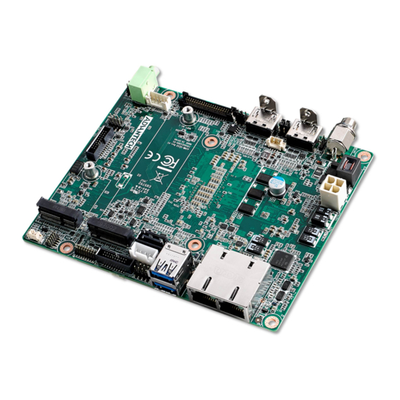
Introduction AIMB-U233 is the newest UTX small form factor motherboard equipped with Intel® 8th Gen Core™ i3-8145UE/i5-8365UE/i7-8665UE processors and DDR4 2400 MHz up to 16 GB. The palm-sized industrial motherboard measures 137 x 112mm and offers fast graphics and media performance to support triple display output via 2 x HDMI1.4b, eDP (or LVDS), and 2 x 10/100/1000 Mbps Ethernet ports offering high-... -
Page 13: Ethernet Lan
Power consumption:+12 V, Windows Idle mode: 6.236 W (i7-8665UE with 16 GB SO-DDR4-2666) Windows Max Load: 22.971 W (i7-8665UE with 16 GB SO-DDR4-2666) Board size: 112 x 137 mm (4.4" x 5.4") Board weight: 3.5 kg AIMB-U233 User Manual... -
Page 14: Jumpers And Connectors
Jumpers and Connectors The AIMB-U233 motherboard is equipped with connectors for linking the board to external devices such as hard disk drives. The board also features several jumpers for configuring the system according to specific applications. The function of each board jumper and connector is listed in the table below. The pro- cedure for setting jumpers is explained in subsequent sections of this chapter. -
Page 15: Board Layout: Jumper And Connector Locations
Board Layout: Jumper and Connector Locations Figure 1.1 Jumper and Connector Locations AIMB-U233 User Manual... -
Page 16: Aimb-U233 Board Diagram
Figure 1.2 Jumper and Connector Locations AIMB-U233 Board Diagram Figure 1.3 AIMB-U233 Board Diagram AIMB-U233 User Manual... -
Page 17: Safety Precautions
Some jumpers comprise a set of three pins, labeled 1, 2, and 3. With these jumpers, simply connect either Pins 1 and 2, or Pins 2 and 3. A pair of needle- nose pliers may be necessary for setting jumpers. AIMB-U233 User Manual... -
Page 18: Cmos Mode Selection (Jcoms1)
Jumper Setting Jumper position for +3.3 V (Default) Jumper position for +5 V Jumper position for +12 V 1.8.4 ATX/AT Mode Selection (PSON1) Table 1.4: ATX/AT Mode selection (PSON1) Function Jumper Setting AT Mode (Default) ATX Mode AIMB-U233 User Manual... -
Page 19: Chapter 2 Connecting Peripherals
Chapter Connecting Peripherals... -
Page 20: Introduction
LAN and USB Ports (LAN12, USB12/USB34) AIMB-U233 provides 2 USB3.2 Gen2 x1 which are located on the rear side. The USB interface complies with the USB specification revision 3.2 that supports transmission rates of up to 10 Gbps and 2 x USB2.0 internal pin header that supports 480 Mbps. -
Page 21: Dc Input Connector (Dcin1)
DC Input Connector (DCIN1) Serial Ports (COM1, COM2, COM3, COM4) AIMB-U233 supports four serial ports. COM1 and COM3 are RS-232. COM2 is RS- 232/422/485 Selected via BIOS) and COM4 is RS-232/422/485 (Selected via BIOS). The IRQ and address ranges for both ports are fixed. However, users can disable the... -
Page 22: Display Port Connector (Hdmi 1/2)
BIOS setup. Users who experience problems with a serial device are advised to check the connector pin assignments. Display Port Connector (HDMI 1/2) System Fan (SYSFAN1) AIMB-U233 User Manual... -
Page 23: Cpu Fan (Cpufan1)
CPU FAN (CPUFAN1) Front Panel Connectors (JFP1) Several external switches are provided for monitoring and controlling the AIMB- U233. AIMB-U233 User Manual... -
Page 24: Atx Soft Power Switch (Jfp1/Reset)
LED (ATX power mode) LED (AT power mode) Power Mode (On/off by momentarily (Powered on/off using the pressing the power button) power supply switch) PSON1 jumper setting Pins 2-3 closed Pins 1-2 closed System On System Off AIMB-U233 User Manual... -
Page 25: Hd Audio Interface Line-Out / Mic-In (Audio1 / Audio2)
HD Audio Interface LINE-OUT / Mic-In (AUDIO1 / AUDIO2) 2.10 Serial ATA Interface (SATA1 and SATAPWR1) AIMB-U233 features a high-performance Serial ATA interface (up to 6 Gb/S). AIMB-U233 User Manual... -
Page 26: At/Atx Mode Selection Connector (Pson1)
2.11 AT/ATX Mode Selection Connector (PSON1) AIMB-U233 supports ATX/AT mode selection by jumper, the default setting is pin 2-3 ATX mode. 2.12 SPI Flash Connector (SPI_CN1) The SPI flash card pin header may be used to flash the BIOS. AIMB-U233 User Manual... -
Page 27: Backlight Inverter Power Connector (Inv1)
2.13 Backlight Inverter Power Connector (INV1) 2.14 LVDS / eDP Panel Connector (LVDS_EDP1), BOM Options AIMB-U233 User Manual... -
Page 28: Lvds Panel Voltage Selection Header (Jlvds1)
2.15 LVDS Panel Voltage Selection Header (JLVDS1) 2.16 General Purpose I/O Connector (GPIO1) AIMB-U233 User Manual... -
Page 29: Cmos Battery Connector (Bat1)
2.17 CMOS Battery Connector (BAT1) 2.18 DDR4 SODIMM (DIMMA1) AIMB-U233 User Manual... -
Page 30: M-Key (Ngff_M1)
2.19 M.2 M-Key (NGFF_M1) 2.20 M.2 B-Key and SIM slot (NGFF_B1 / SIM1) AIMB-U233 User Manual... -
Page 31: E-Key (Ngff_E1)
2.21 M.2 E-Key (NGFF_E1) 2.22 CMOS Clear Pin Header (JCMOS1) AIMB-U233 User Manual... -
Page 32: Low Pin Count Header (Lpc1)
2.23 Low Pin Count Header (LPC1) AIMB-U233 User Manual... -
Page 33: Bios Operation
Chapter BIOS Operation... -
Page 34: Introduction
AIMB-U233 BIOS setup menu pages. BIOS Setup The AIMB-U233 Series is equipped with built-in AMI BIOS and a CMOS Setup Utility that allows users to configure specific settings or activate certain system features. The CMOS Setup Utility saves the configuration in the CMOS RAM of the mother- board. -
Page 35: Main Menu
System Date using the <Arrow> keys. Enter new values via the keyboard. Press the <Tab> or <Arrow> keys to move between fields. The date must be entered in MM/DD/YY format. The time must be entered in HH:MM:SS format. AIMB-U233 User Manual... - Page 36 3.2.1.1 Trusted Computing Security Device Support Enable or Disable BIOS support for security device. AIMB-U233 User Manual...
- Page 37 3.2.1.2 ACPI Settings Enable ACPI Auto Configuration Enable or Disable ACPI Auto Configuration. Enable Hibernation This item allows users to Enable or Disable hibernation. AIMB-U233 User Manual...
- Page 38 ACPI Sleep State This item allows users to set the ACPI sleep state. Lock Legacy Resources This item allows users to lock legacy device resources. 3.2.1.3 Super I/O Configuration AIMB-U233 User Manual...
- Page 39 AIMB-U233 User Manual...
- Page 40 Serial Ports 1/2/3/4 This item allows users to Enable or Disable serial ports 1/2/3/4. Change Settings This item allows users to change the serial port 1/2/3/4 setting. AIMB-U233 User Manual...
- Page 41 3.2.1.4 Hardware Monitor This page shows the AIMB-U233 PC health status. Wake On Ring This item allows users to Enable or Disable Wake On Ring functionality. ACPI Shutdown Temperature This item allows users to set the CPU temperature threshold at which the sys- tem automatically shuts down to prevent the CPU from overheating.
- Page 42 Watchdog Timer This item allows users to Enable or Disable the Watchdog timer. 3.2.1.5 Digital I/O Configuration Digital I/O Configuration This item will allow users to set up Digital I/O 1~16 to “input” or “output”. AIMB-U233 User Manual...
- Page 43 3.2.1.6 Smart Settings Smart Fan Settings Users are allowed to Enable/Disable smart fan and they can also configure smart fan. AIMB-U233 User Manual...
- Page 44 3.2.1.7 S5 RTC Wake Settings Wake System From S5 Enable or Disable system wake on alarm event. AIMB-U233 User Manual...
- Page 45 3.2.1.8 Serial Port Console Redirection Console Redirection This item allows users to Enable or Disable console redirection. AIMB-U233 User Manual...
- Page 46 3.2.1.9 CPU Configuration This page shows CPU Information. Active Processor Cores Number of cores to enable in each processor package. Intel Virtualization Technology AIMB-U233 User Manual...
- Page 47 Intel SpeedStep / Race to Halt / Speed Shift / HDC Control / Turbo Mode C-States Enabled or Disabled Enhanced C-State. C-State Auto Demotion. C-State Un-Demotion. Package C-State Demotion. Package C-State Un-Demotion. CState Pre-Wake Enabled or disabled. IO MWAIT Redirection AIMB-U233 User Manual...
- Page 48 Enabled or disabled. Package C State Limit Package C State Limit Setting. Platform PL1 Enable/Disable Platform PL1. Platform PL2 Enable/Disable Platform PL1. Power Limit 4 Override 3.2.1.10 AMT Configuration AIMB-U233 User Manual...
- Page 49 3.2.1.11 CSM Configuration CSM Support Enable or Disable CSM Support. AIMB-U233 User Manual...
- Page 50 3.2.1.12 NVMe Configuration 3.2.1.13 Network Stack Configuration AIMB-U233 User Manual...
- Page 51 3.2.1.14 USB Configuration AIMB-U233 User Manual...
- Page 52 Mass storage device emulation type. 'AUTO' enumerates devices according to their media format. Optical drives are emulated as 'CDROM', drives with no media will be emulated according to a drive type. USB PWR Configuration (USB Power On/Off Control) AIMB-U233 User Manual...
- Page 53 3.2.1.15 PCI Express Configuration AIMB-U233 User Manual...
- Page 54 3.2.1.16 SATA And RST Configuration SATA Configuration SATA port / SATA mode / RAID Settings. AIMB-U233 User Manual...
-
Page 55: Security
3.2.2 Security This page provides information of the Security on AIMB-U233. 3.2.2.1 Secure Boot Secure Boot Enabled / Disabled. AIMB-U233 User Manual... -
Page 56: Save & Exit
Secure Boot Mode Secure Boot Mode Custom Setting. Restore Factory Key / Restore to Setup mode Key Management 3.2.3 Save & Exit AIMB-U233 User Manual... -
Page 57: Boot
3.2.4 Boot Bootup NumLock State Select the keyboard Numlock state. Quiet Boot Enables or Disables Quiet Boot option. AIMB-U233 User Manual... - Page 58 AIMB-U233 User Manual...
-
Page 59: Software And Service Introduction
Chapter Software and Service Introduction... -
Page 60: Introduction
Introduction The mission of Advantech Embedded Software Services is to “enhance user quality of life with Advantech platforms and Microsoft® Windows® embedded technology.” We equip Advantech platforms with Windows® embedded software products to more effectively support the embedded computing community. This eliminates the hassle of dealing with multiple vendors (hardware suppliers, system integrators, and embed- ded OS distributors) for specific projects. - Page 61 CPU speed according to the system load. System Throttling This refers to a series of methods for reducing system power consumption by lowering the clock frequency. This API allows users to adjust the clock frequency from 87.5% to 12.5%. AIMB-U233 User Manual...
-
Page 62: Software Utility
The Monitoring API is a utility that allows users to monitor the system health indicators, such as voltage, CPU and system temperature, and fan speed. These system values are crucial. If critical errors occur and are not solved imme- diately, permanent damage to the device may result. AIMB-U233 User Manual... -
Page 63: Chipset Software Installation Utility
Chapter Chipset Software Installation Utility... -
Page 64: Before Installation
Before Installation Before installing the enhanced display drivers and utility software, please read the instructions provided in this chapter carefully. The drivers for AIMB-U233 are pro- vided on the Advantech support website: http://support.advantech.com/Support/. This driver will guide and link users to the utilities and drivers required for Microsoft Windows-based systems. -
Page 65: Graphics Setup
Chapter Graphics Setup... -
Page 66: Introduction
See Chapter 5 for information regarding installing the CSI utility. Download the driver from website on your computer. Navigate to the “Graphics” folder and click “setup.exe” to complete the installation of the drivers for Windows 10. AIMB-U233 User Manual... -
Page 67: Lan Configuration
Chapter LAN Configuration... -
Page 68: Introduction
Introduction The AIMB-U233 system features 2 Gigabit Ethernet LANs via dedicated PCI Express x1 lanes (LAN1: Intel Jacksonville: I219LM GbE PHY; LAN2: Intel Springville: I211AT GbE). Features Integrated 10/100/1000 Mbps transceiver Wake-on-LAN (WOL) support PCI Express X1 host interface ... -
Page 69: Appendix A Pin Assignments
Appendix Pin Assignments... -
Page 70: Pin Assignments
USB2.0 Front panel Header USB34 COMS Mode selection JCMOS1 USB3.1 GEN2 Stack connector USB12 Dual port RJ45 Connector LAN1+LAN2 M.2 KEY-B connector NGFF_B1 Nano SIM Card holder SIM1 DDR4 SO-DIMM Socket CH-A DIMMA1 CPU FAN #1 connector CPUFAN1 AIMB-U233 User Manual... -
Page 71: Spi Pin Header (Spi1_Cn1)
SPI Pin Header (SPI1_CN1) Signal Signal SPI_CS0# SPI_PWR SPI_MISO SPI_CLK SPI_MOSI A.1.2 ATX 12V power supply connector (ATX12V1) Signal +12V +12V A.1.3 System Fan #1 connector (SYSFAN1) Signal SYSTEM FAN1 VCC SYSTEM FAN1 SPEED SYSTEM FAN1 PWM AIMB-U233 User Manual... -
Page 72: Dc Input Jack (Dcin1)
IMVP8/9 PMBus KIT (JPMB1) Signal Advantech Define Advantech Define Advantech Define A.1.6 HDMI #1 (HDMI1) Signal Signal TMDS Data2+ TMDS Data2- TMDS Data1+ TMDS Data1- TMDS Data0+ TMDS Data0- TMDS Clock+ TMDS Clock- +5V Power Hot Plug Detect AIMB-U233 User Manual... -
Page 73: At/Atx Mode Selection (Pson1)
LVDS VESA, JEIDA format selection pin header (JLVDS_VCON1) Signal +3.3V Advantech define A.1.9 HDMI #2 (HDMI2) Signal Signal TMDS Data2+ TMDS Data2- TMDS Data1+ TMDS Data1- TMDS Data0+ TMDS Data0- TMDS Clock+ TMDS Clock- +5V Power Hot Plug Detect AIMB-U233 User Manual... -
Page 74: Vdd Select For Lvds1 Panel (Jlvds1)
A.1.11 Low Voltage Differential Signaling / EDP (LVDS_EDP1) LVDS Signal Signal LVDS DETECT# LVDS_OD0- LVDS_ED0- LVDS_OD0+ LVDS_ED0+ LVDS_OD1- LVDS_ED1- LVDS_OD1+ LVDS_ED1+ LVDS_OD2- LVDS_ED2- LVDS_OD2+ LVDS_ED2+ LVDS_OCK- LVDS_ECK- LVDS_OCK+ LVDS_ECK+ LVDS_OD3- LVDS_ED3- LVDS_OD3+ LVDS_ED3+ LVDS ENBKL LVDS VCON AIMB-U233 User Manual... -
Page 75: Inverter Power Connector (Inv1)
Signal Signal LVDS DETECT# EDP_TX2- EDP_TX2+ EDP_TX1- EDP_TX1+ EDP_TX0- EDP_TX0+ EDP_TX3- EDP_TX3+ EDP_AUX+ EDP_AUX- EDP_HPD A.1.12Inverter power connector (INV1) Signal +12V BKL EN BKL CTRL AIMB-U233 User Manual... -
Page 76: Hd Audio Interface (Line-Out) (Audio1)
A.1.14HD Audio Interface (MIC-IN) (AUDIO2) Signal MIC IN - L MIC IN - R Jack Detection A.1.15PWRBTN# / RESET# / HDD LED / PWR LED Header (JFP1) Signal Signal HDD LED+ PWRBTN+ HDD LED- PWRBTN- PWR LED+ RESET+ PWR LED- RESET- AIMB-U233 User Manual... -
Page 77: Com1 And Com2 Box Header (Com12)
DSR# [1] RXD [1] RST# [1] TXD [1] CTS# [1] DTR# [1] RI# [1] DCD# [2] DSR# [2] RXD [2] RST# [2] TXD [2] CTS# [2] DTR# [2] RI# [2] A.1.17Serial ATA interface connector #1 (SATA1) Signal AIMB-U233 User Manual... -
Page 78: Key-M Connector (Ngff_M1)
PERn0 / SATA-B+ PERp0 / SATA-B- PETn0 / SATA-A- PETp0 / SATA-A+ PERST# CLKREQ# REFCLKn PEWAKE# REFCLKp Connector Key Connector Key Connector Key Connector Key Connector Key Connector Key Connector Key Connector Key SUSCLK PEDET +3.3V +3.3V +3.3V AIMB-U233 User Manual... -
Page 79: M.2 Key-E Connector (Ngff_E1)
Connector Key UART TXD UART CTS PETp0 UART RTS PETn0 CL_RST# CL_DAT PERp0 CL_CLK PERn0 COEX3 COEX2 REFCLKp0 COEX1 REFCLKn0 SUSCLK PERST0# CLKREQ0# W_DISABLE2# PEWAKE0# W_DISABLE1# PETp1 PETn1 RESERVED PERp1 PERST1# PERn1 CLKREQ1# PEWAKE1# REFCLKp1 +3.3V REFCLKn1 +3.3V AIMB-U233 User Manual... -
Page 80: Serial Ata Power Connector #1 (Satapwr1)
A.1.20Serial ATA Power connector #1 (SATAPWR1) Signal +12V A.1.21Coin Battery wafer box (BAT1) Signal +VBAT A.1.22Low pin count interface connector (LPC1) Signal Signal LPC CLK LPC AD1 LPC RESET# LPC AD0 LPC FRAME# +3.3V LPC AD3 LPC AD2 AIMB-U233 User Manual... -
Page 81: 16-Bits General Purpose I/O Pin Header (Gpio1)
A.1.24COM3 and COM4 Box Header (COM34) Signal Signal DCD# [3] DSR# [3] RXD [3] RST# [3] TXD [3] CTS# [3] DTR# [3] RI# [3] DCD# [4] DSR# [4] RXD [4] RST# [4] TXD [4] CTS# [4] DTR# [4] RI# [4] AIMB-U233 User Manual... -
Page 82: Usb2.0 Front Panel Header (Usb34)
A.1.25USB2.0 Front panel Header (USB34) Signal Signal VBUS #3 VBUS #4 D- [3] D- [4] D+ [3] D+ [4] A.1.26COMS Mode selection (JCMOS1) Signal VBAT AIMB-U233 User Manual... -
Page 83: Usb3.1 Gen2 Stack Connector (Usb12)
D+ [1] RX- [1] RX+ [1] TX- [1] TX+ [1] VBUS #2 D- [2] D+ [2] RX- [2] RX+ [2] TX- [2] TX+ [2] A.1.28Dual port RJ45 Connector (LAN1+LAN2) Signal MDI0+ MDI0- MDI1+ MDI1- MDI2+ MDI2- MDI3+ MDI3- AIMB-U233 User Manual... -
Page 84: M.2 Key-B (Ngff_B1)
PERp1 / USB3.1-Rx+ UIM - CLK UIM - DATA PETn1 / USB3.1-Tx- UIM - PWR PETp1 / USB3.1-Tx+ PERn0 / SATA-RX+ PERp0 / SATA-RX- PETn0 / SATA-TX- PETp0 / SATA-TX+ PERST# CLKREQ# REFCLKn PEWAKE# REFCLKp RESET# SUSCLK(32kHz) AIMB-U233 User Manual... -
Page 85: Sim Card Holder (Sim1)
A.1.30SIM Card holder (SIM1) Signal SIM PWR SIM RESET SIM CLK SIM VPP SIM DATA A.1.31DDR4 SO-DIMM Socket CH-A (DIMMA1) Please see JEDEC STANDARD. A.1.32CPU FAN #1 connector (CPUFAN1) Signal CPU FAN VCC CPU FAN SPEED CPU FAN PWM AIMB-U233 User Manual... - Page 86 No part of this publication may be reproduced in any form or by any means, electronic, photocopying, recording or otherwise, without prior written permis- sion from the publisher. All brand and product names are trademarks or registered trademarks of their respective companies. © Advantech Co., Ltd. 2020...
Need help?
Do you have a question about the AIMB-U233 and is the answer not in the manual?
Questions and answers