Table of Contents
Advertisement
Quick Links
Advertisement
Table of Contents

Subscribe to Our Youtube Channel
Related Manuals for NXP Semiconductors SJA1105SMBEVM


Summary of Contents for NXP Semiconductors SJA1105SMBEVM
- Page 1 AH1721 SJA1105SMBEVM User Manual Rev. 1.00 — 16 July 2018 User Manual Document information Info Content Keywords SJA1105PQRS, SJA1105S, SJA1105S Evaluation Board, SJA1105SMBEVM, Cascading, Ethernet, Wakeup, Sleep Abstract The SJA1105SMBEVM Evaluation Board is described in this document.
- Page 2 For sales office addresses, please send an email to: mailto:salesaddresses@nxp.com AH1721 All information provided in this document is subject to legal disclaimers. © NXP Semiconductors N.V. 2018. All rights reserved. Rev. 1.00 — 16 July 2018 User Manual 2 of 35...
-
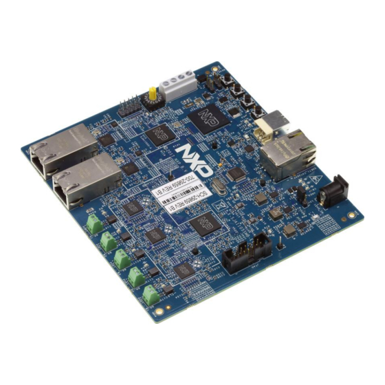
Page 3: Fig 1. Sja1105Smbevm Board
NXP Semiconductors SJA1105SMBEVM UM 1. Introduction The SJA1105SMBEVM (SJA1105S Mother Board Evaluation Module, see Fig 1) is designed for evaluating the capabilities of the SJA1105P/Q/R/S Automotive Ethernet switch family and the TJA1102 Automotive Ethernet PHYs, by developing and running customer software. Therefore, the board features the MPC5748G MCU with a rich set of peripherals for communication and automotive applications. -
Page 4: System Overview
TJA1145FD CAN-Transceiver Product data sheet and Application Hint (AH1309) MPC5748G reference manual If you want to download and run SW on the SJA1105SMBEVM you also need a JTAG- Debug adapter. The easiest solution is the PEMicro “USB Multilink Universal” USB-to- JTAG debug probe (http://www.pemicro.com/products/product_viewDetails.cfm?product_id=15320168), as... -
Page 5: Fig 2. Block Diagram Indicating The Primary Functional Blocks And Interconnections
SJA1105SMBEVM UM Fig 2. Block diagram indicating the primary functional blocks and interconnections The primary functional components of the SJA1105SMBEVM Evaluation Module are: • 1 Microcontroller MPC5748G • 2 switches SJA1105S: ETH-SW(A) and ETH-SW(B) • 3 100BASE-T1 PHYs: ETH-PHY TJA1102 (2*) + TJA1102S •... -
Page 6: Fig 3. Power Supply Topology
4. Hardware Description 4.1 Power The SJA1105SMBEVM is powered by a single 12 Volt input. It is advised to use an adapter that can deliver at least 1 Amp for covering startup current peaks and full-load situations. The nominal current is ~350mA@12V and depends on the number of active PHYs, and if the port is connected to a peer. -
Page 7: Sja1105S Switches
SJA1105 family usable in applications with hard realtime communication requirements. In the SJA1105SMBEVM design, the switches are used in a cascaded topology: the SGMII ports are connected to create a high-speed link for forwarding payload ethernet frames and management data frames. -
Page 8: Tja1102 Phys For 100Base-T1
MACs in the switch or the in the µC to the interface speed. 4.6 CAN interface The SJA1105SMBEVM features a CAN interface, which is implemented with one of the MPC5748G’s FlexCAN-controllers and the TJA1145TK/FD CAN transceiver. In the example project, the CAN-interface is configured with 100kbps and a payload size of 8Byte. -
Page 9: Fig 4. Leds And Connectors
(Mode 1) the LED is on during activity on either TX or RX. AH1721 All information provided in this document is subject to legal disclaimers. © NXP Semiconductors N.V. 2018. All rights reserved. Rev. 1.00 — 16 July 2018 User Manual... -
Page 10: Jumper Blocks And Connectors
1-2: VREG_EN is under control of the PHYs and the processor – see ch 6.3 for sleep/wakeup AH1721 All information provided in this document is subject to legal disclaimers. © NXP Semiconductors N.V. 2018. All rights reserved. Rev. 1.00 — 16 July 2018 User Manual 10 of 35... -
Page 11: Usb Connector
Lauterbach Trace32 for Quorivva presumes an adapter compatible with this standard. J10 uses the following pinning: http://www.ftdichip.com/Products/ICs/FT231X.html AH1721 All information provided in this document is subject to legal disclaimers. © NXP Semiconductors N.V. 2018. All rights reserved. Rev. 1.00 — 16 July 2018 User Manual 11 of 35... -
Page 12: Buttons And Switches
For CAN operation the µC periodically tries to send out a CAN telegram, and reports received telegrams on the serial console. 5. Getting started The following steps are required to bring the SJA1105SMBEVM into operation: 1. Installation of the software development environment S32DS for Power Architecture AH1721 All information provided in this document is subject to legal disclaimers. -
Page 13: Fig 5. S32Ds Installation Packets For Download
AH1721 NXP Semiconductors SJA1105SMBEVM UM 2. Import the example project for SJA1105SMBEVM and build an executable file 3. Flash the executable and start it 4. Connect ethernet stations and send traffic 5. Modify the Software according to the special needs of the project 5.1 Install S32DS... -
Page 14: Fig 6. S32Ds Installing Sdk Update - Step 1
S32DS installing SDK update – step 1 Fig 6. AH1721 All information provided in this document is subject to legal disclaimers. © NXP Semiconductors N.V. 2018. All rights reserved. Rev. 1.00 — 16 July 2018 User Manual 14 of 35... -
Page 15: Fig 7. S32Ds Installing Sdk Update - Step 2
S32DS installing SDK update – step 3 Fig 8. AH1721 All information provided in this document is subject to legal disclaimers. © NXP Semiconductors N.V. 2018. All rights reserved. Rev. 1.00 — 16 July 2018 User Manual 15 of 35... -
Page 16: Fig 9. S32Ds Installing Sdk Update - Step 4
If you use a different project name than “sja1105smbevm_example”, you will later have to adjust the debug setting. AH1721 All information provided in this document is subject to legal disclaimers. © NXP Semiconductors N.V. 2018. All rights reserved. Rev. 1.00 — 16 July 2018 User Manual 16 of 35... - Page 17 (see Fig 10). AH1721 All information provided in this document is subject to legal disclaimers. © NXP Semiconductors N.V. 2018. All rights reserved. Rev. 1.00 — 16 July 2018 User Manual 17 of 35...
-
Page 18: Fig 10. Screenshot Of A Successfully Created Executable
“debug_flash_pemicro” suffix (see Fig 11) AH1721 All information provided in this document is subject to legal disclaimers. © NXP Semiconductors N.V. 2018. All rights reserved. Rev. 1.00 — 16 July 2018 User Manual 18 of 35... -
Page 19: Fig 11. Screenshot Of The Debug Configuration Popup Window Part1
Fig 12. Screenshot of the debug configuration popup window part2 AH1721 All information provided in this document is subject to legal disclaimers. © NXP Semiconductors N.V. 2018. All rights reserved. Rev. 1.00 — 16 July 2018 User Manual 19 of 35... -
Page 20: Fig 13. Screenshot Of The Debug Configuration Popup Window Part3
Fig 13. Screenshot of the debug configuration popup window part3 • Make sure you have the debug adapter connected to the PC, and the SJA1105SMBEVM connected to the adapter and powered up before continuing. • When activating the debug configuration, you can see the actions behind the scenes on the console window. -
Page 21: Fig 14. Screenshot Of A Debug Session
SJA1105SMBEVM UM Fig 14. Screenshot of a debug session AH1721 All information provided in this document is subject to legal disclaimers. © NXP Semiconductors N.V. 2018. All rights reserved. Rev. 1.00 — 16 July 2018 User Manual 21 of 35... -
Page 22: Example Software Features
ProcessorExpert in the ENET device driver. o For 100BASE-T1 ports, the Link LED indicates an established link. All 100BASE-T1 ports on the SJA1105SMBEVM take the master role, so the peers must be configured for slave, so that a link can come up. This can be changed by SW, but it is not implemented in the delivered example. -
Page 23: Fig 15. Software Components And Layers
PHYs) but also special PHYs, like the TJA110x family. This driver uses the AH1721 All information provided in this document is subject to legal disclaimers. © NXP Semiconductors N.V. 2018. All rights reserved. Rev. 1.00 — 16 July 2018 User Manual... - Page 24 S32DS. The components used in the example project are all preconfigured to the needs for the actual HW components used on the SJA1105SMBEVM board, and the smooth interaction with the application layer and communication peers. The configuration is done interactively within the Eclipse framework.
-
Page 25: Code Organization
GPIOs, device handles, etc. This data is used by other application components to call the right device driver instances. o SJA1105SMBEVM utilities: sja1105smbevm_console.c contains some very simple functions for implementing a serial console. This is useful for debugging, and very simple visualization. -
Page 26: Fig 16. Organization Of Example Project Source Code
(.c and .h files) is copied from the SDK distribution directory to this project specific AH1721 All information provided in this document is subject to legal disclaimers. © NXP Semiconductors N.V. 2018. All rights reserved. Rev. 1.00 — 16 July 2018 User Manual... -
Page 27: Changing The Static Switch Configuration Stream
• Sources: This is where the application code is located. There is the SJA1105PQRS device driver, the board specific modules in sja1105smbevm, the application modules and main.c • Debug_FLASH and/or Debug_RAM are directories, which contain everything, what the S32DS tools create during the project build phase, depending on which build configuration is active. -
Page 28: Fig 17. Switch Configuration Files
4. Edit the copies of the configuration source files, modify them as desired and save them. AH1721 All information provided in this document is subject to legal disclaimers. © NXP Semiconductors N.V. 2018. All rights reserved. Rev. 1.00 — 16 July 2018 User Manual 28 of 35... -
Page 29: Fig 18. Hw Support For Wakeup And Sleep Applications
8. Rebuild the project 6.4 Wakeup and Sleep The SJA1105SMBEVM hardware allows applications to send the board to sleep mode, and to get woken up either by a remote wakeup command received over one of the communication links, or by a local event, represented by a pushbutton. A simplified schematic is shown in Fig 18. -
Page 30: Abbreviations
General Purpose Input Output Graphical User Interface Integrated Circuit AH1721 All information provided in this document is subject to legal disclaimers. © NXP Semiconductors N.V. 2018. All rights reserved. Rev. 1.00 — 16 July 2018 User Manual 30 of 35... - Page 31 Unshielded Twisted Pair – a standard for ethernet cables for e.g. 10BASE-T µC Microcontroller Universal Serial Bus AH1721 All information provided in this document is subject to legal disclaimers. © NXP Semiconductors N.V. 2018. All rights reserved. Rev. 1.00 — 16 July 2018 User Manual 31 of 35...
-
Page 32: Legal Information
In no event shall NXP Semiconductors be liable for any indirect, incidental, punitive, special or consequential damages (including - without limitation -... -
Page 33: Table Of Contents
HW support for wakeup and sleep applications ................ 29 AH1721 All information provided in this document is subject to legal disclaimers. © NXP Semiconductors N.V. 2018. All rights reserved. Rev. 1.00 — 16 July 2018 User Manual 33 of 35... -
Page 34: List Of Tables
Rotary switch configuration in the example project ............. 12 Table 8. Abbreviations ..........30 AH1721 All information provided in this document is subject to legal disclaimers. © NXP Semiconductors N.V. 2018. All rights reserved. Rev. 1.00 — 16 July 2018 User Manual 34 of 35... -
Page 35: Contents
List of figures ............. 33 List of tables ............34 Contents ............. 35 AH1721 All information provided in this document is subject to legal disclaimers. © NXP Semiconductors N.V. 2018. All rights reserved. Rev. 1.00 — 16 July 2018 User Manual 35 of 35...
Need help?
Do you have a question about the SJA1105SMBEVM and is the answer not in the manual?
Questions and answers