Table of Contents
Advertisement
Quick Links
UM11316
MIFARE SAM AV3 evaluation board
Rev. 1.1 — 12 March 2020
586311
Document information
Information
Content
Keywords
MIFARE SAM AV3, demo board, LPC, X-mode, S-mode, I2C, SPI, CLRC663
Abstract
This manual shows how to operate the MIFARE SAM AV3 demo board, how
to jumper the interfaces and how to use the demo board with all different
mode configurations of MIFARE SAM AV3
User manual
COMPANY PUBLIC
Advertisement
Table of Contents

Related Manuals for NXP Semiconductors MIFARE SAM AV3


Summary of Contents for NXP Semiconductors MIFARE SAM AV3
- Page 1 MIFARE SAM AV3, demo board, LPC, X-mode, S-mode, I2C, SPI, CLRC663 Abstract This manual shows how to operate the MIFARE SAM AV3 demo board, how to jumper the interfaces and how to use the demo board with all different mode configurations of MIFARE SAM AV3...
- Page 2 UM11316 NXP Semiconductors MIFARE SAM AV3 evaluation board Revision history Date Description 20200312 Added section about use with RFIDDiscover, added known Limitations, corrected typos 20200108 Initial version UM11316 All information provided in this document is subject to legal disclaimers. © NXP B.V. 2020. All rights reserved.
-
Page 3: Introduction
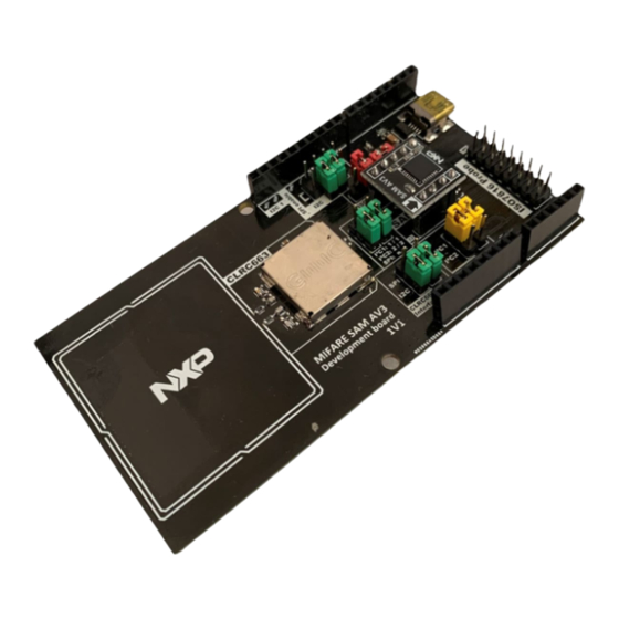
Introduction Figure 1. MIFARE SAM AV3 evaluation board The MIFARE SAM AV3 offers various different modes of operation, interfaces and other configuration settings. The MIFARE SAM AV3 evaluation board shall help to evaluate these modes all on a single Arduino shield shaped board, in combination with any MCU. -
Page 4: Schematics
Figure 2. MIFARE SAM AV3 evaluation board - Power management The MIFARE SAM AV3 evaluation board is equipped with a mini-USB port to power the system. The port is only used for power, it is not used for any communication/debug etc. -
Page 5: Arduino ® R3 Header
MIFARE SAM AV3 evaluation board Figure 4. MIFARE SAM AV3 evaluation board - Antenna matching The MIFARE SAM AV3 evaluation board also has a CLRC663 contactless frontend directly built-in, which can be interfaced via SPI, and I C. All Interfacing options are available and can be configured by jumpers. - Page 6 C interface selection jumper from the MCU, the I C interface is forced to 3V3. This way, either 5 V or 3V3 MCU's can be used. As the MIFARE SAM AV3 is powered by 3V3, the I C interface voltage on SDA must not exceed this value. The SCL line of this interface is shifted down to 1V8 directly on the MIFARE SAM Av3 add-on board.
-
Page 7: Mifare Sam Av3
SUBD-15 adapter cable. 2.4.1 Add-on board The MIFARE SAM AV3 itself is placed on an add-on board, to be able to easily exchange the MIFARE SAM AV3 in case it has been misconfigured. The pullups for the MCU_I2C_xxx interface, as well as the voltage level divider for the MCU_I2C_SCL is directly placed on the add-on board. - Page 8 UM11316 NXP Semiconductors MIFARE SAM AV3 evaluation board Figure 8. MIFARE SAM AV3 evaluation board - MIFARE SAM AV3 add-on board UM11316 All information provided in this document is subject to legal disclaimers. © NXP B.V. 2020. All rights reserved.
-
Page 9: Jumper Setting
MIFARE SAM AV3 evaluation board Jumper Setting Figure 9. MIFARE SAM AV3 evaluation board - MIFARE SAM AV3 The MIFARE SAM AV3 evaluation board comes with 3 different colors of Jumpers: • Green: Configuration of RC663 interfaces • Yellow: MCU_I2C interface selection •... -
Page 10: Spi
In case SPI is selected, the jumpers on the SPI header need to be inserted, to connect the SPI interface from the MCU to the CLRC663. This setting is intended to use the MIFARE SAM AV3 in S-mode, or in an S/X mixed variant. Figure 11. SPI header UM11316 All information provided in this document is subject to legal disclaimers. -
Page 11: I2C
At this point, the MCU can already control the CLRC663 via SPI. 3.1.2 I2C In case I2C is selected, the CLRC663 will be controlled by the MIFARE SAM AV3 in X- mode. 2 jumpers need to be inserted in the SPI header, these correspond to the ADR0 and ADR1 pins on the CLRC663 host interface in I2C configuration. -
Page 12: Mcu Interface Selection
MIFARE SAM AV3. If not, then an additional SPI connection for the MCU to the CLRC663 is needed, to activate the SAM interface. 3.2 MCU Interface Selection The connection between the MIFARE SAM AV3 and the MCU is done by either of the 2 ® supported I C interface locations on the Arduino R3 header. -
Page 13: Mifare Sam Av3
C was already done in the previous chapters. The only thing left to do is the VDD of the MIFARE SAM AV3. VDD is selected on JP9, the options are permanent 3V3 or IO6 on the Arduino header. Permanent 3V3 means that the MIFARE SAM AV3 will stay in the state it is, until the whole board is power cycled. - Page 14 MIFARE SAM AV3 evaluation board Figure 16. VCC selection of MIFARE SAM AV3 In case a user wants to access the MIFARE SAM AV3 via the ISO7816 SmartCard interface, a Jumper needs to be placed on the ISO7816 header (JP7). Important: In this...
-
Page 15: Mifare Sam Av3 Configuration
MIFARE SAM AV3 evaluation board MIFARE SAM AV3 Configuration In the default configuration of MIFARE SAM AV3, it expects a PN523 reader frontend for X-mode communication. This needs to be changed using the SAM_SetConfig command once. The command looks like the following: 80 3C 01 00 01 03 Table 2. SetConfiguration for reader frontend selection... -
Page 16: Modes Of Operation
MIFARE SAM AV3 evaluation board Modes of Operation 5.1 X-mode The easiest way to get started with the MIFARE SAM AV3 evaluation board is to operate the MIFARE SAM AV3 in X-mode. An example configuration for this would look like the following Figure 18. X-mode example configuration... -
Page 17: Mixed Mode
NXP Semiconductors MIFARE SAM AV3 evaluation board In this S-mode configuration, the MIFARE SAM AV3 is not connected to the CLRC663. The host MCU controls the CLRC663 via the SPI interface, and the MIFARE SAM AV3 via I 5.3 Mixed mode Figure 20. X/S mixed configuration... -
Page 18: Rfiddiscover
ISO7816 interface. This opens up the possibility of also performing cold resets on the MIFARE SAM AV3, while the CLRC663 stays powered. In this configuration, The MIFARE SAM AV3 evaluation board can be used with a PC/SC reader together with RFIDDiscover, to fully explorer all features of MIFARE SAM AV3 in X-mode. -
Page 19: First Steps On A New Mifare Sam Av3 Evaluation Board
SetConfiguration commands have been executed before, as described in Section 4 5.4.1.1 First Steps on a new MIFARE SAM AV3 Evaluation Board The easiest way of getting stared with the MIFARE SAM AV3 evaluation board is using the tool RFIDDiscover v. 4.7+ and the Evaluation Board Connected via the ISO7816- probe and a contact reader. - Page 20 Step 2: Activate MIFARE SAM AV3 To activate the MIFARE SAM AV3, navigate to the MIFARE SAM AV3 tab, which can be found in the top right of the window. In the menu on the left, choose "SAM AV3 → SAM Host Communication →...
- Page 21 → Host authentication", and click on "AuthHost". The "Ref Key" can be the same key as used before to activate the MIFARE SAM AV3. The "H/W Keystore" (→ MIFARE SAM AV3) Ref Key needs to be No. 00, version 00, which is the MIFARE SAM AV3 master key.
- Page 22 Figure 27. Host Authentication Step 4: Set the configuration Now, the SetConfiguration command can be used to configure the MIFARE SAM AV3 to the correct parameters for the Evaluation Board. The reader IC needs to be set to RC663, the I C processing clock speed to 0x06.
- Page 23 MIFARE SAM AV3 evaluation board Figure 28. SetConfiguration Step 5: RC_Init As a last step, the MIFARE SAM AV3 needs to establish an I C connection to the CLRC663 reader frontend. This is done via the RC_Init command. If all above steps were successful, just press the button "RC_Init", which should result in a SUCCESS.
- Page 24 UM11316 NXP Semiconductors MIFARE SAM AV3 evaluation board Figure 29. RC_Init From now on, the Evaluation Board will connect to RFIDDiscover already after the "New Profile" dialog without an error message. The software automatically performs a Host Authentication and RC_Init, therefore the board is ready to use right after connecting.
-
Page 25: Known Limitations
X-mode I2C interface pins (IO2 and IO3) of the SAM AV3 are at a higher voltage level as VCC, due to the I2C pullups. This is not allowed according to the MIFARE SAM AV3 data sheet, and results in security reset events. - Page 26 UM11316 NXP Semiconductors MIFARE SAM AV3 evaluation board Figure 31. Add new I2C pullups to SAM VCC on bottom side of the PCB This modification has no influence on any mode of operation. UM11316 All information provided in this document is subject to legal disclaimers.
-
Page 27: References
UM11316 NXP Semiconductors MIFARE SAM AV3 evaluation board References 1. Data sheet – MIFARE SAM AV3, document number DS3235xx. 2. User manual – RFIDDiscover, document number UM2538xx. 3. RFIDDiscover – RFIDDiscover v 4.7+, software number SW186647, available on docstore UM11316 All information provided in this document is subject to legal disclaimers. -
Page 28: Legal Information
In no event shall NXP Semiconductors, its affiliates or their suppliers be liable to customer for any special, indirect, consequential, punitive or incidental damages (including without limitation 8.2 Disclaimers... - Page 29 UM11316 NXP Semiconductors MIFARE SAM AV3 evaluation board Tables Tab. 1. Abbreviations .............3 Tab. 3. SAM_SetConfiguration for I2C processing Tab. 2. SetConfiguration reader frontend clock speed ............. 15 selection ............15 UM11316 All information provided in this document is subject to legal disclaimers.
- Page 30 MIFARE SAM AV3 evaluation board - Power Fig. 15. MCU_I2C selection ......... 13 management ............4 Fig. 16. VCC selection of MIFARE SAM AV3 ....14 Fig. 3. MIFARE SAM AV3 evaluation board - Fig. 17. ISO7816 configuration of the MIFARE SAM CLRC663 ............4...
-
Page 31: Table Of Contents
Mixed mode ............. 17 ISO7816 Interface ..........17 5.4.1 RFIDDiscover ...........18 5.4.1.1 First Steps on a new MIFARE SAM AV3 Evaluation Board ..........19 Known Limitations ..........25 References ............27 Legal information ..........28 Please be aware that important notices concerning this document and the product(s) described herein, have been included in section 'Legal information'.
Need help?
Do you have a question about the MIFARE SAM AV3 and is the answer not in the manual?
Questions and answers