
Related Manuals for 360 Vision PRED-3M


Summary of Contents for 360 Vision PRED-3M
- Page 1 Predator Installation Manual Ver 2.9 Page 1 Predator Installation/Configuration Manual © 360 Vision Technology Ltd.
-
Page 2: Table Of Contents
10 OSD Operation/Navigation ........................21 11 Special Presets ............................25 12 Important - Care of Painted Surfaces ..................... 26 13 Storage and Handling..........................26 14 Warranty ..............................26 15 Camera Specification ..........................27 16 PSU Enclosure ............................27 © 360 Vision Technology Ltd. -
Page 3: Safety And Precautions
8. Connection of data signals and power should only be made using a pre-made Predator Composite cables. 9. Use only 360 Vision Predator power supplies. These have suitable terminals for all the wires in the Predator composite cable. - Page 4 ANY THIRD PARTY WITHOUT THE DIRECT WRITTEN ALL DIMENSIONS IN MM Manor Park, Runcorn, Cheshire, APPROVED: PART NUMBER: X.X = PERMISSION OF THE AUTHOR. WA7 1SY. United Kingdom. M5702- REMOVE ALL SHARP EDGES 3rd ANGLE PROJECTION X.XX = 0.05 RELEASED: www.360visiontechnology.com © 360 Vision Technology Ltd.
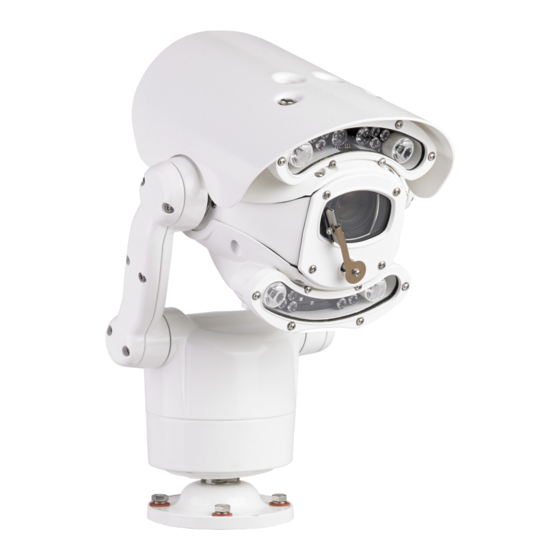
- Page 5 Page 5 Weight 8kg Predator Single Lamps (Straight Arm version) - Covers IR75, IR125 or IR100WL versions. Weight 9kg Predator Thermal with Lamps - Covers IR (75m IR) or IRW (75m IR, 50m White Light) versions. © 360 Vision Technology Ltd.
- Page 6 All version of the Predator can be built to order with the integral HMA (Hinged Mount Adapter). The HMA is fitted during manufacture and is NOT available as an option for the installer to add to an existing Predator. © 360 Vision Technology Ltd.
-
Page 7: Bracket Dimensional Drawing
Predator Installation Manual Ver 2.9 Page 7 3 Bracket Dimensional Drawing Weight 1.2kg Predator Wall Bracket Weight 2.2kg Predator Corner Bracket Weight 2.5kg Predator PMB Bracket © 360 Vision Technology Ltd. - Page 8 PERMISSION OF THE AUTHOR. Please use the appropriate fixings to suit the weight of the camera housing used. WA7 1SY. United Kingdom. REMOVE ALL SHARP EDGES M5350-A 3rd ANGLE PROJECTION X.XX = 0.05 RELEASED: www.360visiontechnology.com © 360 Vision Technology Ltd.
-
Page 9: Connections
Predator 12-way connector pin-out. Socket 12-pin socket (solder side view) Socket 12-pins: Wiring diagram of socket fitted fitted by 360 Vision to the composite cable by 360 Vision to the composite cable Coax Core (A) Coax Core (A) Brown (L) - Page 10 Predator Installation Manual Ver 2.9 Page 10 BLACK 24Vac(-) BROWN 24Vac(+) WHITE 24Vac(-) GREY 24Vac(+) GREEN 24Vac(-) PINK 24Vac(+) Coax Screen (TC) Coax Core (TC) RS485 D- ORANGE RS485 D+ Coax Screen Coax Core © 360 Vision Technology Ltd.
- Page 11 Predator Installation Manual Ver 2.9 Page 11 BLACK 24Vac(-) BROWN 24Vac(+) WHITE 24Vac(-) GREY 24Vac(+) GREEN 24Vac(-) PINK 24Vac(+) Coax Screen (TC) Coax Core (TC) RS485 D- ORANGE RS485 D+ Coax Screen Coax Core © 360 Vision Technology Ltd.
-
Page 12: Standalone Alarmcard Setup
Connect RS485 to camera to CON5. Protocol/Alarm settings Relay Output Use CON4 to set protocol and camera Use CON3 for relay output. alarm behaviour. (see page 14). Alarm Inputs Use CON1 for volt free alarm inputs. © 360 Vision Technology Ltd. - Page 13 Address 1 to 128 range See below Dil Switch Settings Normally Open Contacts Normally Closed Contacts (un-used inputs must be connected to common) RS485 Address Settings Switch is shown as white. Example shows switch settings for camera address 3 © 360 Vision Technology Ltd.
-
Page 14: Washer Control Pcb Setup
Connect RS485 from controller to CON5. RS485 Out Connections Pre-wired RS485 to camera from CON6. Power Connections Pre-wired 24Vac to CON7. Inputs CON4 CON1 not used. Aux Settings Aux 2 (Pelco default) Aux 3 (Pelco D 2400 only) © 360 Vision Technology Ltd. -
Page 15: Rs422/Rs485 Converter
Page 15 4.3 RS422/RS485 Converter RS422 Tx/Termination LK2 RS485 Use CON4 for RS422 Tx Pre-wired CON3 for RS485 to camera. RS422 Rx/Termination LK1 Use CON2 for RS422 Rx Power Pre-wired CON1 for 24Vac power connection. © 360 Vision Technology Ltd. - Page 16 Predator Installation Manual Ver 2.9 Page 16 BLACK 24Vac(-) BROWN 24Vac(+) WHITE 24Vac(-) GREY 24Vac(+) GREEN 24Vac(-) PINK 24Vac(+) Coax Screen (TC) Coax Core (TC) RS485 D- ORANGE RS485 D+ Coax Screen Coax Core © 360 Vision Technology Ltd.
-
Page 17: Predator Washer/Nozzle Bracket
Predator’s rotating body. Take care that the cable ties do not cause excessive restriction of the tube. Water Jet direction (vertical) Adjustable Nozzle Tube Nozzle Bracket located Fit M8 Plain Washer Between Nozzle Bracket and Predator Mounting Base. K.Craik 15-08-2016 © 360 Vision Technology Ltd. -
Page 18: Connections To Predators With Hma
Use BNC Video 2 for thermal video connection from Predator. Please make sure there is adequate spare cable (20cm) for when the camera is resting on the lanyard, failure to do this could damage the connector circuit board. © 360 Vision Technology Ltd. -
Page 19: Basic Twisted Pair/Rs485 Data Wiring
8 Predator Protocol/Address setup. All Predator cameras are supplied set to 360 Vision protocol, camera twisted pair address 1. When the Predator is switched on, an OSD (On Screen Display) is shown on the image from the camera for approx 20 seconds. -
Page 20: Predator Osd
Predator Installation Manual Ver 2.9 Page 20... -
Page 21: Osd Operation/Navigation
The camera will perform an ACTION (goto preset, start preset or mimic tour), after a period of inactivity. Use the NUMBER option to set which preset or tour to start, and the DELAY MINUTES/SECONDS to input the inactivity time period. © 360 Vision Technology Ltd. - Page 22 Predator Installation Manual Ver 2.9 Page 22 General Settings Menu Offers more camera options. General 1 Digital Zoom - Use this option to enable or disable digital zoom. • White Balance - Change the camera white balance settings to suit the area. •...
- Page 23 White When Alarm - Set if white lights are to be used if an alarm is triggered. This feature works with • 360 Standalone alarmcard or 360 Vision Matrix only. White Timeout - Use if a white light timer is required. Default is on.
- Page 24 • 40% lamp intensity • 60% lamp intensity • 80% lamp intensity • 100% lamp intensity • video switch • white day • ir-mono • mono • normal night • washer on • washer off © 360 Vision Technology Ltd.
-
Page 25: Special Presets
Program/Recall Power on Park preset position. Define 151 Set Left Side White Light See Page 23 Exclusion Define 152 Set Right Side Seek 240 Bright Control Seek 249 Bright Control (On) (change to set brightness level) (Off) © 360 Vision Technology Ltd. -
Page 26: Important - Care Of Painted Surfaces
©2015 ALL DESIGNS AND SPECIFICATIONS ARE SUBJECT TO CHANGE WITHOUT NOTICE © 360 Vision Technology Ltd. -
Page 27: Camera Specification
4 levels ( 3 fixed preset, 1 user defined) Operating temperature -40°C ~ 60°C with optional heater Power 24Vac/dc Certification CE approval : IP68 16 PSU Enclosure Material PC/ABS Dimensions (PRED-PSU-SM enclosure) 255 x 180 x 100mm © 360 Vision Technology Ltd. - Page 28 Predator Installation Manual Ver 2.9 Page 28 © 360 Vision Technology Ltd.
Need help?
Do you have a question about the PRED-3M and is the answer not in the manual?
Questions and answers