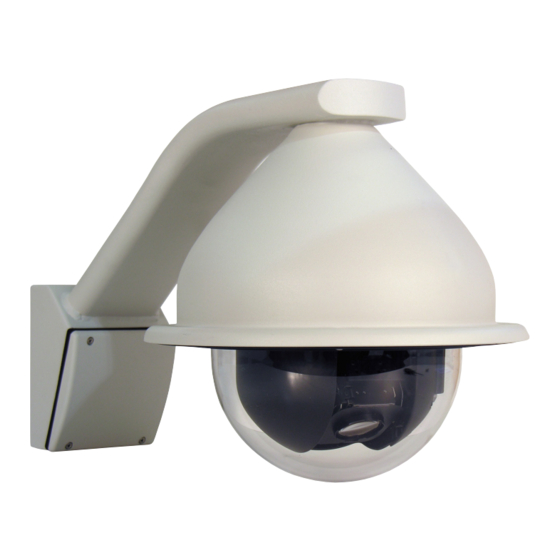
Summary of Contents for 360 Vision VisioniDome
- Page 1 Vision i Dome_VisionDome Installation Manual Ver 2.10 Page 1 Vision i Dome/VisionDome Installation/Configuration Manual © 360 Vision Technology Ltd.
-
Page 2: Table Of Contents
11.1 PIN Number ............................ 16 12 OSD Operation/Navigation ........................17 13 Special Presets ............................19 14 Important - Care of Painted Surfaces ..................... 19 15 Storage and Handling..........................19 16 Warranty ..............................19 18 Notes ..............................20 © 360 Vision Technology Ltd. -
Page 3: Safety And Precautions
Vision i Dome_VisionDome Installation Manual Ver 2.10 Page 3 1 Safety and Precautions 1. Please read these notes before attempting to operate the 360 Vision VisionDome-HD, and keep for future reference. 2. All servicing and repairs must be handled by 360 Vision Technology. -
Page 4: Bracket Dimensional Drawing
Internal Pendant 3 Bracket Dimensional Drawing 246 mm LOCKING SCREW TWIST CAMERA ONTO WALL BRACKET AND SECURE USING CAMERA COVER LOCKING SCREW TWIST ACRYLIC ONTO DOME COVER Weight: 1.6kg Internal Pole Bracket Internal Wall Bracket © 360 Vision Technology Ltd. -
Page 5: Mounting Options
Vision i Dome_VisionDome Installation Manual Ver 2.10 Page 5 4 Mounting Options Weight: 2kg Internal Corner Bracket External Corner Bracket Please use the appropriate fixings to suit the weight of the camera housing used. 5 Connections © 360 Vision Technology Ltd. - Page 6 Vision i Dome_VisionDome Installation Manual Ver 2.10 Page 6 © 360 Vision Technology Ltd.
-
Page 7: Standalone Alarmcard Setup
Relay Output (0.5A 125Vac max, 1A 24Vdc max) Protocol/Alarm settings Use CON3 for relay output. Use CON4 to set protocol and camera alarm behaviour. (see page 9). Alarm Inputs Use CON1 for volt free alarm inputs. © 360 Vision Technology Ltd. - Page 8 Address 1 to 128 range See below Dil Switch Settings Normally Open Contacts Normally Closed Contacts (un-used inputs must be connected to common) RS485 Address Settings Switch is shown as white. Example shows switch settings for camera address 3 © 360 Vision Technology Ltd.
- Page 9 Power 1.25mm² 125 metres 50 metres 1.50mm² 150 metres 60 metres 2.00mm² 250 metres 100 metres To ensure optimum Visiondome performance these parameters must be adhered to. Failure to do so will invalidate the warranty. © 360 Vision Technology Ltd.
- Page 10 White with Blue Band Pin 6 Green RS485 D- Pin 7 White with Brown Band Pin 8 Brown RJ45 CON3 Connections A Twisted Pair Video balun is required to suit cable length to receive video signal. © 360 Vision Technology Ltd.
-
Page 11: Basic Twisted Pair/Rs485 Data Wiring
A RS485 star driver/data distribution product must be used. All cameras in this wiring configuration must have the RS485 (end of line) termination on. See Section 7 or 8 for the relevant product, termination switch settings. © 360 Vision Technology Ltd. -
Page 12: Vision I Dome
Ultrak (RS485) Vista (RS485)** released March 2015. Mark Mercer (RS485)*** released August 2015. * Special order for Vision i Dome, please make the 360 Vision sales team aware of your requirements. 7.2 Address/Termination Switch (S2) Dil Switch Settings Dome Address 1 to 128 range... -
Page 13: Visiondome
RS485 Termination On (Last camera in chain) Switch is shown as white. Dil Switch Settings 360 Vision (Coax or RS485) Pelco D 9600 baud (or Coaxitron Extended) Pelco D 4800 baud (or Coaxitron Extended) Example shows switch Pelco D 2400 baud (or Coaxitron Extended) -
Page 14: Address Switch (S1)
9 RS485 Address Settings Switch is shown as white. Use S1 on the VisionDome for addressing. Use S2 on the Vision i Dome for addressing (Limited to 128). Example shows switch settings for camera address 3 © 360 Vision Technology Ltd. -
Page 15: Vision I Dome Osd
Vision i Dome_VisionDome Installation Manual Ver 2.10 Page 15 Vision i Dome Configuration © 360 Vision Technology Ltd. -
Page 16: Visiondome Osd
Vision i Dome_VisionDome Installation Manual Ver 2.10 Page 16 VisionDome Configuration © 360 Vision Technology Ltd. -
Page 17: Osd Operation/Navigation
The camera will perform an ACTION (goto preset, start preset or mimic tour), after a period of inactivity. Use the NUMBER option to set which preset or tour to start, and the DELAY MINUTES/SECONDS to input the inactivity time period. © 360 Vision Technology Ltd. - Page 18 • Define Privacy Zone - Used to set a privacy zone. • Seek Privacy Zone - Used to seek a privacy zone. • Remove Privacy Zone - Used to remove a privacy zone. © 360 Vision Technology Ltd.
-
Page 19: Special Presets
©2015 ALL DESIGNS AND SPECIFICATIONS ARE SUBJECT TO CHANGE WITHOUT NOTICE © 360 Vision Technology Ltd. -
Page 20: Notes
Vision i Dome_VisionDome Installation Manual Ver 2.10 Page 20 18 Notes © 360 Vision Technology Ltd. - Page 21 Vision i Dome_VisionDome Installation Manual Ver 2.10 Page 21 © 360 Vision Technology Ltd.
- Page 22 Vision i Dome_VisionDome Installation Manual Ver 2.10 Page 22 © 360 Vision Technology Ltd.


Need help?
Do you have a question about the VisioniDome and is the answer not in the manual?
Questions and answers