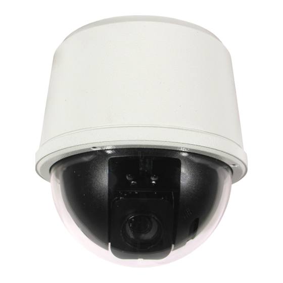
Summary of Contents for 360 Vision Visiondome-VR
- Page 1 Visiondome VR Installation Manual Ver 2.7 Page 1 Visiondome-VR Installation/Configuration Manual © 360 Vision Technology Ltd.
-
Page 2: Table Of Contents
11 Storage and Handling ..........................15 12 Warranty ..............................15 1 Safety and Precautions 1. Please read these notes before attempting to operate the 360 Vision VisionDome VR, and keep for future reference. 2. All servicing and repairs must be handled by 360 Vision Technology. -
Page 3: Housing Dimensional Drawing
ANY THIRD PARTY WITHOUT THE DIRECT WRITTEN ALL DIMENSIONS IN MM Manor Park, Runcorn, Cheshire, APPROVED: PART NUMBER: X.X = PERMISSION OF THE AUTHOR. WA7 1SY. United Kingdom. M5725-A REMOVE ALL SHARP EDGES 3rd ANGLE PROJECTION RELEASED: X.XX = 0.05 www.360visiontechnology.com © 360 Vision Technology Ltd. -
Page 4: Mounting Options
ALL DIMENSIONS IN MM APPROVED: Manor Park, Runcorn, Cheshire, X.X = PERMISSION OF THE AUTHOR. WA7 1SY. United Kingdom. REMOVE ALL SHARP EDGES 3rd ANGLE PROJECTION X.XX = 0.05 RELEASED: www.360visiontechnology.com 3 Mounting Options Weight 2.2kg Corner Bracket © 360 Vision Technology Ltd. -
Page 5: Connections
3 year warranty. RS485 Data Data + Blue Data - Yellow Power V + (AC) Brown V - (AC) Blue Video Video Signal Centre Core Video Ground Coax Shield © 360 Vision Technology Ltd. - Page 6 MAINS input 230Vac VRVD-PSU VRVD-PSU_301117 Enclosure Dimensions 180 x 180 x 100mm MAINS FUSE VRVD-XALARM-PSU MAINS FUSE = 1.0AF OUTPUT FUSE VRVD-XALARM-PSU FUSE 1 = 2.5AT FUSE 2 = 200mAT MAINS input 230Vac VRVD-XALARM-PSU VRVD-XALARM-PSU_301117 © 360 Vision Technology Ltd.
-
Page 7: Standalone Alarmcard Setup
Relay Output (0.5A 125Vac max, 1A 24Vdc max) Protocol/Alarm settings Use CON3 for relay output. Use CON4 to set protocol and camera alarm behaviour. (See page 9). Alarm Inputs Use CON1 for volt free alarm inputs. © 360 Vision Technology Ltd. - Page 8 Address 1 to 128 range See below Dil Switch Settings Normally Open Contacts Normally Closed Contacts (un-used inputs must be connected to common) Switch is shown as RS485 Address Settings white. Example shows switch settings for camera address 3 © 360 Vision Technology Ltd.
-
Page 9: Basic Twisted Pair/Rs485 Data Wiring
RS485 twisted pair cable is wired to each camera in a “star” from one point. A suitable RS485 star driver/data distribution product must be used. All cameras in this wiring configuration must have the RS485 (end of line) termination on. © 360 Vision Technology Ltd. -
Page 10: Visiondome Vr Protocol/Address Setup
6 Visiondome VR Protocol/Address setup. All Visiondome VR cameras are supplied set to 360 Vision protocol, camera twisted pair address 1. When the Visiondome VR is switched on, an OSD (On Screen Display) is shown on the image from the camera for approx 20 seconds. -
Page 11: Visiondome Vr Osd
Visiondome VR Installation Manual Ver 2.7 Page 11 © 360 Vision Technology Ltd. -
Page 12: Osd Operation/Navigation
The camera will perform an ACTION (goto preset, start preset or mimic tour), after a period of inactivity. Use the NUMBER option to set which preset or tour to start, and the DELAY MINUTES/SECONDS to input the inactivity time period. © 360 Vision Technology Ltd. - Page 13 Power Reset - This will reboot the camera, no settings will be lost. • Factory Reset - This will reboot the camera and all the settings will be lost. • Visiondome VR Software Version - This shows the software version of the camera. © 360 Vision Technology Ltd.
-
Page 14: Special Presets
When the Visiondome VR is installed in areas where there is a high risk of damage from birds or their droppings, additional precautions and measures should be used to keep the birds away from the Visiondome VR e.g. fit anti-bird spikes. © 360 Vision Technology Ltd. -
Page 15: Storage And Handling
©2017 ALL DESIGNS AND SPECIFICATIONS ARE SUBJECT TO CHANGE WITHOUT NOTICE © 360 Vision Technology Ltd. - Page 16 Visiondome VR Installation Manual Ver 2.7 Page 16 © 360 Vision Technology Ltd.


Need help?
Do you have a question about the Visiondome-VR and is the answer not in the manual?
Questions and answers