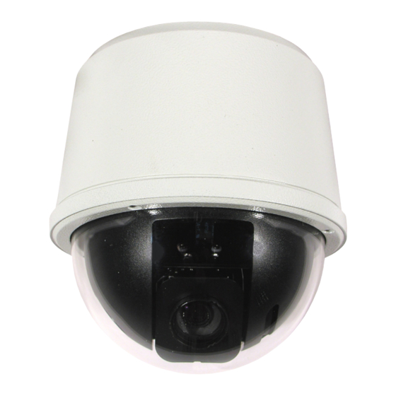
Summary of Contents for 360 Vision Vision i Dome
- Page 1 Vision i Dome_VisionDome VR Installation Manual Ver 3.1 Page 1 Vision i Dome/VisionDome VR Installation/Configuration Manual © 360 Vision Technology Ltd.
-
Page 2: Table Of Contents
7.1 Protocol Switch (S2) ......................... 13 7.2 Address Switch (S1) ......................... 14 8 RS485 Address Settings .......................... 14 9 Vision i Dome OSD ..........................15 9.1 PIN Number ............................. 15 10 VisionDome OSD ..........................16 10.1 PIN Number ........................... 16 11 OSD Operation/Navigation ........................ -
Page 3: Safety And Precautions
Vision i Dome_VisionDome VR Installation Manual Ver 3.1 Page 3 1 Safety and Precautions 1. Please read these notes before attempting to operate the 360 Vision VisionDome-HD, and keep for future reference. 2. All servicing and repairs must be handled by 360 Vision Technology. - Page 4 ANY THIRD PARTY WITHOUT THE DIRECT WRITTEN SWN-N ALL DIMENSIONS IN MM Manor Park, Runcorn, Cheshire, APPROVED: X.X = PERMISSION OF THE AUTHOR. WA7 1SY. United Kingdom. REMOVE ALL SHARP EDGES 3rd ANGLE PROJECTION RELEASED: X.XX = 0.05 www.360visiontechnology.com © 360 Vision Technology Ltd.
-
Page 5: Bracket Dimensional Drawing
TWIST ACRYLIC ONTO DOME COVER Weight: 1.6kg Internal Pole Bracket Internal Wall Bracket Weight: 2.2kg Internal Corner Bracket External Corner Bracket Please use the appropriate fixings to suit the weight of the camera housing used. © 360 Vision Technology Ltd. -
Page 6: Connections
Vision i Dome_VisionDome VR Installation Manual Ver 3.1 Page 6 4 Connections © 360 Vision Technology Ltd. - Page 7 Vision i Dome_VisionDome VR Installation Manual Ver 3.1 Page 7 © 360 Vision Technology Ltd.
-
Page 8: Standalone Alarmcard Setup
Vision i Dome_VisionDome VR Installation Manual Ver 3.1 Page 8 The VRVD-XALARM-PSU has eight normally open/normally closed (Dilswitch S1, switch 8 on) alarm inputs on connector CON1 on the alarm PCB. When using normally closed contacts, all un-used alarm inputs must be connected to alarm in common CON1. - Page 9 Address 1 to 128 range See below Dil Switch Settings Normally Open Contacts Normally Closed Contacts (un-used inputs must be connected to common) RS485 Address Settings Switch is shown as white. Example shows switch settings for camera address 3 © 360 Vision Technology Ltd.
- Page 10 Power 1.25mm² 125 metres 50 metres 1.50mm² 150 metres 60 metres 2.00mm² 250 metres 100 metres To ensure optimum Visiondome performance these parameters must be adhered to. Failure to do so will invalidate the warranty. © 360 Vision Technology Ltd.
- Page 11 Vision i Dome_VisionDome VR Installation Manual Ver 3.1 Page 11 Internal Vision i Dome/VisionDome Connections The connection board is located at the top of the dome. Coax Video Connection board Power Connections Connect 24Vac to CON2. Data Connections Connect RS485 (D+/D-) to Dome connection board using CON3.
-
Page 12: Basic Twisted Pair/Rs485 Data Wiring
Page 12 5 Basic Twisted Pair/RS485 Data Wiring The Vision i Dome and VisionDome are capable of being controlled by either Coax Telemetry or Twisted Pair Telemetry (RS485). Below are wiring configurations for two wiring formats used for Twisted Pair Telemetry (RS485). -
Page 13: Visionidome
RS485 Termination On (Last camera in chain) Switch is shown as white. Dil Switch Settings 360 Vision (Coax or RS485) Pelco D 9600 baud (or Coaxitron Extended) Pelco D 4800 baud (or Coaxitron Extended) Example shows switch Pelco D 2400 baud (or Coaxitron Extended) -
Page 14: Address Switch (S1)
8 RS485 Address Settings Switch is shown as white. Use S1 on the VisionDome for addressing. Use S2 on the Vision i Dome for addressing (Limited to 128). Example shows switch settings for camera address 3 © 360 Vision Technology Ltd. -
Page 15: Vision I Dome Osd
Vision i Dome_VisionDome VR Installation Manual Ver 3.1 Page 15 Vision i Dome Configuration © 360 Vision Technology Ltd. -
Page 16: Visiondome Osd
Vision i Dome_VisionDome VR Installation Manual Ver 3.1 Page 16 VisionDome VR Configuration... -
Page 17: Osd Operation/Navigation
A maximum of four individual tours of presets can be stored in each VisionDome. Each tour can have between 2 and 360 points, each point can be a preset in the range 1 to 360 (36 presets for the Vision i Dome). Different points can use any preset number, including repeats of ones that have been used before. - Page 18 Line Phase - (Not available on Vision i Dome) Can be used to manually adjust the line phase. • Video Gain - (Not available on Vision i Dome) Used to adjust the video level to suit different lengths of coax cable.
-
Page 19: Important - Care Of Painted Surfaces
Vision i Dome_VisionDome VR Installation Manual Ver 3.1 Page 19 Privacy Zone Menu (Not available on Vision i Dome) Can be used to obscure a scene within an image e.g. private residence. Move the camera to the position required for the privacy zone before going into the camera OSD. You cannot manually move the camera once in the OSD. - Page 20 Vision i Dome_VisionDome VR Installation Manual Ver 3.1 Page 20 © 360 Vision Technology Ltd.


Need help?
Do you have a question about the Vision i Dome and is the answer not in the manual?
Questions and answers