Table of Contents
Advertisement
Quick Links
Advertisement
Table of Contents

Related Manuals for Fantini Cosmi CH130RR


Summary of Contents for Fantini Cosmi CH130RR
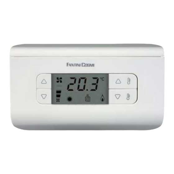
- Page 1 AMBIENT THERMOSTAT FOR FAN-COILS WITH ACTUATOR...
-
Page 2: Table Of Contents
TABLE OF CONTENTS Thermostat confi guration .........10 Technical features of the thermostat ......13 Introduction ..............3 DIN bar CH172D actuator ........13 Controls and signals ..........4 Application and use .........13 Controls .............4 Fastening and connecting .......14 Signals ...............4 Operation check ..........14 User’s manual ............5 Electric connections ........15 “Summer / Winter”... -
Page 3: Introduction
Introduction The settings and data are store in a permanent This fan-coil thermostat control kit CH130RR memory that will retain them even when the is made up of a CH130R thermostat and a DIN thermostat is not connected to the CH172D. -
Page 4: Controls And Signals
Controls and signals Signals Controls 1. Measured temperature 2. “Comfort” symbol 3. “Economy” symbol 4. “Summer” symbol 1. Fan speed increase button 5. “Winter” symbol 2. Fan speed decrease button 6. Fan speed symbols 3. Selected program temperature value 7. System “ON” in summer operation increase button 4. -
Page 5: User's Manual
User’s manual “Summer / Winter” selection To start the thermostat after the same has To switch from the “Winter” operation (i.e. heat- been installed, proceed as follows: ing system) to the “Summer” operation (i.e. cooling system), and vice versa, press the 1+2 1. -
Page 6: Operating Modes
Operating modes “Economy” operating mode The CH130R thermostat features three dif- With the “Economy” operating mode, the ther- ferent manual operating modes: “Comfort”, mostat regulates the heating or cooling system “Economy”, and the “OFF” function (OFF). operation in order to always keep the same economy temperature set. -
Page 7: Off" Function (Off)
Maintenance “OFF” function (OFF) The “OFF” function can be achieved by setting The thermostat should be cleaned by using the fan speed to zero: in this case, the thermo- a soft cotton cloth. No detergent should be stat will carry out no heat regulation, not even used. -
Page 8: Fastening The Socket
Fastening the socket pole connector is located in the right bottom The thermostat is supplied complete with a corner. socket suitable for mounting both on the wall and to rectangular or round built-in 3-seat To ensure correct operation, the socket shall boxes (503). - Page 9 Actuator connection External probe connection Connect the power supply wires running from Connect the two external probe wires with the CH172D actuator with terminals A and B, screwed terminals “1” and “2”, as illustrated in as illustrated in the fi gure. the fi...
-
Page 10: Fastening The Thermostat Onto The Socket
Fastening the thermostat onto the socket The confi guration parameters are represented Insert and screw the thermostat down to the by an index (P01, P02…) on the display and socket (make sure that the multi-pole connec- by pressing buttons “1” and “2”, the parameter tor is engaged correctly). - Page 11 P01: Type of system. Index Parameter Values Preset 1 two-tube system: the thermostat will drive only the valve (ON/OFF type) used for heat- Type of system ing both during the heating and the cooling: in fact, the valve will control both hot water and External probe 3-4-5 cold water.
- Page 12 P03: display visualization (“Comfort” and “Economy”) in the heating 1 ambient temperature: the ambient tempera- mode. ture will be shown on the display. 2 set-point: the current set point will be shown P10: “Summer” lower limit set-point tem- on the display. perature It can be adjusted from 2.0 to 40.0°C.
-
Page 13: Technical Features Of The Thermostat
Technical features of the thermostat Power supply By means of the Complying with the EN60730-1, EN60730- CH172D actuator standards Outputs Actuator controls ErP classifi cation: ErP Class IV; 2% (EU Reg. 811/2013 - 813/2013) Inputs External probe input Electric connections Screwed terminals DIN bar CH172D actuator Protection degree... -
Page 14: Fastening And Connecting
Fastening and connecting Operation check The unit has been designed to be built in (in- Refer to the specifi c user manual for the in- side fan-coils, special panels or other suitable struction on how to use the CH130R thermo- housings). -
Page 15: Electric Connections
Electric connections Connecting several actuators with a ther- mostat A CH130R is able to control up to fi ve fan-coils CH130R at the same time, by making use of only two ca- V p. supply bles to get connected with the actuators. One E.V. -
Page 16: Technical Features Of The Actuator
Technical features of the actuator Complying with the EN60730-1 Power supply 230V 50 Hz standards Absorbed power Disconnection type 1B (micro-disconnec- Input Thermostat controls tion) Relay output features 5(3)A250 V~ Pulse voltage 4000V Type of assembling DIN bar Voltage-free switching 2 valve outputs contacts Dimensions... - Page 17 Fantini Cosmi S.p.A. reserve the right to make any necessary technical and construction modifi cation without any obligation to give prior notice.
- Page 18 NOTES NOTE...
- Page 19 DISPOSAL OF PRODUCTS The crossed out wheeled dust bin symbol indicates that products must be collected and disposed of separately from household waste. Integrated batteries and accumulators can be disposed of with the product. They will be separated at the recycling centres. The black bar indicates that the product was placed on the market after August 13, 2005.
- Page 20 FANTINI COSMI S.p.A. Via dell’Osio, 6 20090 Caleppio di Settala, Milano - ITALY Tel. +39 02 956821 Fax +39 02 95307006 | info@fantinicosmi.it EXPORT DEPARTMENT Ph +39 02 95682229 export@fantinicosmi.it www.fantinicosmi.com...
Need help?
Do you have a question about the CH130RR and is the answer not in the manual?
Questions and answers