
Subscribe to Our Youtube Channel
Related Manuals for Kramer KDS-8-MNGR


Summary of Contents for Kramer KDS-8-MNGR
- Page 1 USER MANUAL MODEL: KDS-8-MNGR SDVoE Manager P/N: 2900-301456 Rev 1 www.kramerAV.com...
-
Page 2: Table Of Contents
Monitoring and Controlling Decoders and Encoders Configuring the System Configuring System Settings Configuring Transmitters Configuring Receivers Defining Output Resolution Configuring Video Walls Configuring Multiviews Technical Specifications Default Communication Parameters Video Specifications Acronyms Telnet Control RS-232 and Telnet Commands KDS-8-MNGR – Contents... -
Page 3: Introduction
Kramer Electronics Ltd. Introduction Welcome to Kramer Electronics! Since 1981, Kramer Electronics has been providing a world of unique, creative, and affordable solutions to the vast range of problems that confront the video, audio, presentation, and broadcasting professional on a daily basis. In recent years, we... - Page 4 European Advanced Recycling Network (EARN) and will cover any costs of treatment, recycling and recovery of waste Kramer Electronics branded equipment on arrival at the EARN facility. For details of Kramer’s recycling arrangements in your particular country go to our recycling pages at www.kramerav.com/support/recycling.
-
Page 5: Overview
A trigger input interface is also provided to allow the easy addition of a Kramer Control remote keypad, or other trigger-supporting products, which can be installed within a podium or table in a conference room or classroom. -
Page 6: Typical Applications
KDS-8-MNGR is ideal for the following typical applications: • Video/TV wall display and control. • Security surveillance and control. • Commercial advertising, display and control. • Home theaters with smart home controls. • Retail sales and demonstration. KDS-8-MNGR – Introduction... -
Page 7: Defining Kds-8-Mngr
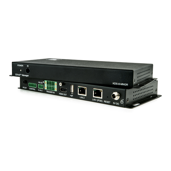
Kramer Electronics Ltd. Defining KDS-8-MNGR Front and Back Panel Figure 1: KDS-8-MNGR SDVoE Manager Front Panel Feature Function POWER LED Lights when the device receives power. IR Window Figure 2: KDS-8-MNGR SDVoE Manager Rear Panel Feature Function IR EXT Port For future use. - Page 8 5V DC Port Plug the 5V DC power adapter into the unit and connect it to an AC wall outlet for power. (Optional, not required if the unit is powered via PoE). KDS-8-MNGR – Defining KDS-8-MNGR...
-
Page 9: Connecting Kds-8-Mngr
Always switch off the power to each KDS-8 device before connecting it to your KDS-8-MNGR. After connecting your KDS-8-MNGR, connect its power and then switch on the power to each device. Figure 3: Connecting to the KDS-8-MNGR To connect KDS-8-MNGR as illustrated in the above example: 1. -
Page 10: Rs-232 Pinout And Defaults
3. Highlight the network adapter you want to use to connect to the device and click Change settings of this connection. The Local Area Connection Properties window for the selected network adapter appears as shown in Figure KDS-8-MNGR – Connecting KDS-8-MNGR... - Page 11 (TCP/IPv4) depending on the requirements of your IT system. 5. Click Properties. The Internet Protocol Properties window relevant to your IT system appears as shown in Figure 5 Figure Figure 5: Internet Protocol Version 4 Properties Window KDS-8-MNGR – Connecting KDS-8-MNGR...
- Page 12 You can connect the Ethernet port of KDS-8-MNGR to the Ethernet port on a network hub or using a straight-through cable with RJ-45 connectors. Configuring Ethernet Port You can set the Ethernet parameters via the embedded Web pages. KDS-8-MNGR – Connecting KDS-8-MNGR...
-
Page 13: Using Embedded Web Pages
33. • Configuring Transmitters on page 45. • Configuring Receivers on page 47. • Defining Output Resolution on page 49. • Configuring Video Walls on page 50. • Configuring Multiviews on page 51. KDS-8-MNGR – Using Embedded Web Pages... - Page 14 If a keyboard is not available, such as when using a touch screen, an on-screen keyboard can be activated by clicking on the keyboard icon ( The default user name and password is admin. Figure 8: Accessing the Embedded Web Pages KDS-8-MNGR – Using Embedded Web Pages...
-
Page 15: Discovering Ip Address
2. View the IP address or change it as follows: a. Connect a mouse to the USB port on the rear panel. b. Click to open a keyboard on-screen to enter text. c. Click Login. The Login window appears. Figure 10: Login Window KDS-8-MNGR – Using Embedded Web Pages... -
Page 16: Monitoring And Controlling Decoders And Encoders
KDS-8F. Units that were previously a part of the system, but are not currently detected will still be displayed, however they will have a disconnected icon ( ) and cannot be used for routing. KDS-8-MNGR – Using Embedded Web Pages... - Page 17 The encoder/decoder does not support the video thumbnail feature. The encoders’ source streams are collectively exceed the 10Gbps bandwidth limitation. The encoder/decoder is offline or currently not detected by KDS-8-MNGR. KDS-8-MNGR features automatic bandwidth reduction if the total source streaming exceeds 10Gbps.
- Page 18 2. Click and drag a source button in the transmitter area to a predefined Video group or an All button in the receiver area. 3. Release the mouse button. The routed source name appears below the group name. The source on the encoder is streamed to multiple decoders. KDS-8-MNGR – Using Embedded Web Pages...
- Page 19 For example, Video Wall 1 group shows as Group: Video Wall 1 on the right side of the Video wall section. • Transmitter area, which includes all the available decoders. • Video wall view area, representing the selected video wall. KDS-8-MNGR – Using Embedded Web Pages...
- Page 20 An active preset appears has green windows that show a faded video thumbnail of the source that is currently selected. • Transmitter area, which includes all the encoder sources. Unavailable sources are displayed in red. KDS-8-MNGR – Using Embedded Web Pages...
- Page 21 The HDMI Audio page includes two main areas. The: • HDMI Audio Transmitter area, which includes drag-and-drop buttons for all the encoder sources that are detected by the system, and a multi-option stop button to stop video transmission. KDS-8-MNGR – Using Embedded Web Pages...
- Page 22 The selected source and routed displays change their color. You can also drag and drop display decoders to an encoder source on the transmitter side to activate a new streaming route. The source on the encoder is streamed to the decoder. KDS-8-MNGR – Using Embedded Web Pages...
- Page 23 3. Click and drag the display to the Stop button. 4. Release the mouse. Streaming to that display stops. Drag All button down to the Stop button to stop all streaming. Display streaming has stopped. KDS-8-MNGR – Using Embedded Web Pages...
- Page 24 23. • Streaming an Analog Audio Source to Multiple Decoders on page 23. • Stopping an Analog Audio Source Stream on page 24. • Stopping an HDMI Audio Display Stream on page 24. KDS-8-MNGR – Using Embedded Web Pages...
- Page 25 3. Click and drag a source button in the transmitter area to a predefined HDMI audio group or an All button in the receiver area. 4. Release the mouse button. The routed source name appears below the group name. The source on the encoder is streamed to multiple decoders. KDS-8-MNGR – Using Embedded Web Pages...
- Page 26 • USB Device area, which includes drag-and-drop buttons for all the decoder USB device endpoints and a Stop button to stop communication from a device. KDS-8-MNGR – Using Embedded Web Pages...
- Page 27 1. In the Menu tabs, select Monitor & Control. The Video page appears. 2. Click USB. The USB page appears. 3. Click and drag a USB host button to the Stop button in the Host area. Communication from USB host has stopped. KDS-8-MNGR – Using Embedded Web Pages...
- Page 28 2. Click IR. The IR page appears. Figure 17: Monitor & Control Tab – IR Page 3. Click and drag an IR input button from the Input side to All on the Output side. KDS-8-MNGR – Using Embedded Web Pages...
- Page 29 Sender area, which includes drag-and-drop buttons for all the encoder RS-232 ports that are detected by the system, and a stop button to stop RS-232 streaming to the encoders. • Receiver area, which includes drag-and-drop buttons for all the decoder RS-232 output ports. KDS-8-MNGR – Using Embedded Web Pages...
- Page 30 The selected input and output devices change their color. RS-232 inputs on the sender side can also be dragged and dropped onto RS-232 outputs to activate a new route. RS-232 output is routed to RS-232 Input. KDS-8-MNGR – Using Embedded Web Pages...
- Page 31 2. Click Macro. The RS-232 page appears. Figure 19: Monitor & Control Tab – Macro Page 3. Click a Macro. the selected Macro button remains blue until execution completion of the selected Macro. Macro is activated. KDS-8-MNGR – Using Embedded Web Pages...
-
Page 32: Configuring The System
4. Click Save. By default, both LAN ports are set to DHCP mode. The current IP address can be verified using the HDMI output or RS-232 if the Device Discovery software is not available. KDS-8-MNGR – Using Embedded Web Pages... - Page 33 Reset all transmitters to reset all detected transmitters back to their factory default settings. ▪ Reset all receivers to reset all detected receivers back to their factory default settings. ▪ Reboot System to reboot this KDS-8-MNGR unit. KDS-8-MNGR – Using Embedded Web Pages...
- Page 34 1. In the Menu tabs, select System. The System page appears. Figure 21: System Page 2. Under IP Master Controller (KDS-8-MNGR), click Choose file. The file selection window opens. 3. Select the firmware update file (*.bin format) located on your local PC.
-
Page 35: Configuring System Settings
A/V, USB or IR/RS- 232 sources. Once created, each group appears within the appropriate section of the Monitor & Control Tab (see Monitoring and Controlling Decoders and Encoders on page 14) beside standard receivers. KDS-8-MNGR – Using Embedded Web Pages... - Page 36 In the Group area, which lists the devices in the group, click a device button to remove it from the group (back to the Device area) or click Remove All to remove all of them. 4. Click Save Group. A group is saved to the list. KDS-8-MNGR – Using Embedded Web Pages...
- Page 37 Select the command type from the drop-down list. c. Select the other parameters relevant for this command type (Transmitter and Receiver for this command). d. Set the command order in the macro sequence. KDS-8-MNGR – Using Embedded Web Pages...
- Page 38 4. For IR: a. Select the command target from the drop-down box. b. Enter or copy the command to the empty area below IR. c. Click Send to send the command immediately. RS-232/IR command is sent. KDS-8-MNGR – Using Embedded Web Pages...
- Page 39 2. Click I/O Trigger. The I/O Trigger page appears. Figure 25: Settings Tab – I/O Trigger Page 3. Select the Macro from the drop-down list under a trigger. A macro is assigned to a Trigger. KDS-8-MNGR – Using Embedded Web Pages...
- Page 40 3840×2160p@30Hz (10.2Gbps) & Deep Color (8/10/12-bit), LPCM 7.1 & Bitstream STD UHD+ 2CH 3840×2160p@60Hz (18Gbps) & Deep Color (8/10/12-bit), LPCM 2.0 STD UHD+ MCH 3840×2160p@60Hz (18Gbps) & Deep Color (8/10/12-bit), LPCM 7.1 & Bitstream KDS-8-MNGR – Using Embedded Web Pages...
- Page 41 5. Click Sync to force the unit to sync to the NTP server. KDS-8-MNGR’s clock does not have a battery backup, so time is not kept once the unit is unplugged. However, the time will automatically sync at power up if an internet connection is available and the NTP server is valid.
- Page 42 Figure 28: Settings Tab – Schedule Page 3. Click to create a new schedule. Click to edit an existing schedule. Click to delete a schedule 4. Enter Schedule Name. 5. Next to Activate, Enable or Disable the current schedule event. KDS-8-MNGR – Using Embedded Web Pages...
- Page 43 8. Click Date text box for a one-time macro execution. A calendar window opens: Figure 30: Activate Date – Calendar Window 9. Click Now to change the date and time to the present. Figure 31: Setting Present Date and Time KDS-8-MNGR – Using Embedded Web Pages...
- Page 44 5. Next to Activate, enable or disable the current schedule event. 6. Next to Macro, select the macro (from the drop-down list) to activate at the scheduled time. 7. Next to Mode, select Repeat. Figure 32: Settings Tab – Schedule Page KDS-8-MNGR – Using Embedded Web Pages...
- Page 45 11. Click Times box to set the number of times this macro will be executed from the set date and on. Select 0 to have this schedule run repeatedly. Figure 34: Date – Repeat Scheduling Window 12. Click Save Schedule. Schedule is set to repeat a set number of times. KDS-8-MNGR – Using Embedded Web Pages...
- Page 46 7. Next to Mode, select Weekly. The Week Scheduling setting appears. Figure 35: Scheduling – Date Mode 8. Click Activate Date box. A calendar window opens: Figure 36: Activate Date – Calendar Window KDS-8-MNGR – Using Embedded Web Pages...
-
Page 47: Configuring Transmitters
2. Perform the following actions: ▪ Under Hello, Click a button in the list. The relevant encoder POWER LED flashes to help you identify that encoder in the system. Click again to return to normal operation. KDS-8-MNGR – Using Embedded Web Pages... - Page 48 Under USB, click Settings to view and change USB settings via the USB pop-up window. Click Save to accept changes and exit window. USB functionality is not supported by all SDVoE units. Encoder Settings are configured. KDS-8-MNGR – Using Embedded Web Pages...
-
Page 49: Configuring Receivers
47. • Removing a Decoder on page 49. Viewing and Configuring Decoder Settings To view and configure decoder settings: 1. In the Menu tabs, select Receiver. The Receiver page appears. Figure 39: Receiver Page KDS-8-MNGR – Using Embedded Web Pages... - Page 50 Select a System Command to the unit (such as factory reset, Reboot the unit, firmware update and transform transceiver to receiver), change the device name, and so on. Click Save to accept changes and exit window. Figure 40: Receiver Page – Device Settings KDS-8-MNGR – Using Embedded Web Pages...
-
Page 51: Defining Output Resolution
Since scaling applies only to the decoder side, a change in the resolution does not affect bandwidth usage. To define the output resolution: 1. In the Menu tabs, select Scaling. The Scaling page appears. Figure 41: Scaling Page KDS-8-MNGR – Using Embedded Web Pages... -
Page 52: Configuring Video Walls
Video wall groups are displayed in the Monitor & Control tab in the same order. ▪ Enter Group Name. ▪ Select the encoder to use as the video source for the video wall. KDS-8-MNGR – Using Embedded Web Pages... -
Page 53: Configuring Multiviews
When using 4K sources, we recommend that you enable the “Multiview Divide FPS by two” feature on the encoder. KDS-8-MNGR – Using Embedded Web Pages... - Page 54 Selecting Full Screen stretches the source to fit the video wall, regardless of the original source’s aspect ratio. This setting applies to all sources/windows within the current Multiview preset. KDS-8-MNGR – Using Embedded Web Pages...
- Page 55 6. Click Execute to save the changes to the current video wall configuration and then execute the changes. If the video wall is not already active, this action activates it. Video wall is configured. KDS-8-MNGR – Using Embedded Web Pages...
-
Page 56: Technical Specifications
Shipping Dimensions (W, D, H) 38.2cm x 18.8cm x 6cm (15" x 7.4" x 2.4") Net Weight 0.65kg (1.4lbs) approx. Shipping Weight 1.15kg (2.5lbs) approx. Accessories Included Power adapter and cord Specifications are subject to change without notice at www.kramerav.com KDS-8-MNGR – Technical Specifications... -
Page 57: Default Communication Parameters
848×480p@60 1024×768p@60/70/75/85 1152×864p@75 1280×720p@50/60 1280×768p@60/75/85 1280×800p@60/75/85 1280×960p@60/85 1280×1024p@60/75/85 1360×768p@60 1366×768p@60 1400×1050p@60 1440×900p@60/75 1600×900p@60RB 1600×1200p@60 1680×1050p@60 1920×1080i@50/60 1920×1080p@24/25/30 1920×1080p@50/60 1920×1200p@60RB KDS-8-MNGR – Technical Specifications... - Page 58 4K@24/25/30Hz & 4K@50/60Hz (4:2:0), 8-bit color ▪ Data rates higher than 5.3Gbps or above 225MHz TMDS clock but below 10.2Gbps • 4K60 (4K UHD+ Video) ▪ 4K@50/60Hz (4:4:4, 8-bit) ▪ 4K@50/60Hz (4:2:0, 10-bit HDR) Data rates higher than 10.2Gbp KDS-8-MNGR – Technical Specifications...
-
Page 59: Acronyms
Graphical User Interface HDCP High-bandwidth Digital Content Protection HDMI High-Definition Multimedia Interface High Dynamic Range HDTV High-Definition Television IGMP Internet Group Management Protocol Internet Protocol Infrared Keyboard/Video/Mouse Local Area Network Light-Emitting Diode LPCM Linear Pulse-Code Modulation Media Access Control KDS-8-MNGR – Acronyms... -
Page 60: Telnet Control
N1 netmask get uart 2 mode set macro N1 run get lan N1 gateway set uart 2 command [N1] set lan N1 static ipaddr N2 set voip N1 audio out oN2 route N3 n4 KDS-8-MNGR – Telnet Control... - Page 61 Reset the unit to the factory defaults. get command ver get command ver Show the unit’s current command version. get model name get model name Show the unit’s model name. get model type get model type Show the unit’s product type. KDS-8-MNGR – Telnet Control...
- Page 62 2 ........[LAN Port 2] get lan N1 ipconfig get lan N1 ipconfig Show the specified LAN port’s current IP configuration information. Available values for N1: 1 ........[LAN Port 1] 2 ........[LAN Port 2] KDS-8-MNGR – Telnet Control...
- Page 63 N2 = X.X.X.X ....[X = 0~255, IP address] get lan N1 static ipaddr get lan N1 static ipaddr Show the specified LAN port’s current static IP address. Available values for N1: 1 ........[LAN Port 1] 2 ........[LAN Port 2] KDS-8-MNGR – Telnet Control...
- Page 64 List all available serial ports. set uart N1 reset set uart N1 reset Reset the specified serial port’s settings to the factory defaults. Available values for N1: 1 ........[3-pin serial port] 2 ........[5-pin serial port] KDS-8-MNGR – Telnet Control...
- Page 65 N1 stop bit get uart N1 stop bit Show the current number of stop bits for the specified serial port. Available values for N1: 1 ........[3-pin serial port] 2 ........[5-pin serial port] KDS-8-MNGR – Telnet Control...
- Page 66 2 mode N1 set uart 2 mode N1 Set the operational mode of the Control Output (5-pin) serial port. Available values for N1: 0 ........[Disabled] 1 ........[RS-232 mode] 2 ........[RS-422 mode] 3 ........[RS-485 mode] KDS-8-MNGR – Telnet Control...
- Page 67 1 ........[HDMI audio output] 2 ........[Analog audio output] N2 = tx1~tx128 ....[Transmitter device ID] Available values for N3: 1 ........[HDMI audio input] 2 ........[Analog audio input] Note: The values for N1 and N3 must match. KDS-8-MNGR – Telnet Control...
- Page 68 Available values for N1: tx1~tx128 ......[Transmitter device ID (Tx pin)] rx1~rx128 ......[Receiver device ID (Tx pin)] Available values for N2: tx1~tx128 ......[Transmitter device ID (Rx pin)] rx1~rx128 ......[Receiver device ID (Rx pin)] KDS-8-MNGR – Telnet Control...
- Page 69 Available values for N1: tx1~tx128 ......[Transmitter device ID (IR output)] rx1~rx128 ......[Receiver device ID (IR output)] Available values for N2: tx1~tx128 ......[Transmitter device ID (IR input)] rx1~rx128 ......[Receiver device ID (IR input)] KDS-8-MNGR – Telnet Control...
- Page 70 N1 set multiview preset N1 Execute the specific multiview preset. N1 = 1~128 ....... [Multiview preset ID] set macro N1 run set macro N1 run Execute the specified macro immediately. N1 = 1~16 ......[Macro ID] KDS-8-MNGR – Telnet Control...
- Page 71 This limited warranty gives you specific legal rights, and you may have other rights which vary from country to country or state to state. This limited warranty is void if (i) the label bearing the serial number of this product has been removed or defaced, (ii) the product is not distributed by Kramer Electronics or (iii) this product is not purchased from an authorized Kramer Electronics reseller.
- Page 72 SAFETY WARNING Disconnect the unit from the power supply before opening and servicing For the latest information on our products and a list of Kramer distributors, visit our website where updates to this user manual may be found. We welcome your questions, comments, and feedback.
Need help?
Do you have a question about the KDS-8-MNGR and is the answer not in the manual?
Questions and answers