Advertisement
Scan for full manual
Step 1: Check what's in the box
VP-427X 4K HDBT/HDMI Receiver/Scaler
1 Bracket set
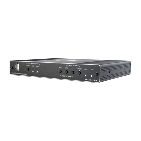
Step 2: Get to know your VP-427X
#
Feature
1
PROG USB Connector
2
INPUTS
SELECT Button
3
HDBT LED
4
HDMI LED
5
MENU Button
6
ENTER Button
–
7
8
FREEZE/+ Button
9
LINK LED
10
ON LED
11
INPUTS
HDBT RJ-45 Connector
12
HDMI Connector
13
OUTPUT
HDMI Connector
AUDIO 5-pin Terminal
14
Block Connector
15
REMOTE Contact-Closure 4-pin
Terminal Block Connector
16
RS-232
CONTROL 3-pin Terminal
Block Connector
17
DATA 3-pin Terminal
Block Connector
RELAY 3-pin Terminal Block
18
Connector
19
12V DC Connector
Step 3: Mount VP-427X
Install VP-427X using one of the following methods:
•
Attach the rubber feet and place the unit on a flat surface.
•
Fasten a bracket (included) on each side of the unit and attach it to a flat surface
www.kramerav.com/downloads/VP-427X
(see
•
Mount the unit in a rack using the recommended rack adapter
www.kramerav.com/product/VP-427X
(see
VP-427X Quick Start
VP-427X Quick Start Guide
This guide helps you install and use your
Go to
www.kramerav.com/downloads/VP-427X
upgrades are available.
Function
Connect to a USB stick to perform firmware upgrades.
Press to select the input (HDBT or HDMI).
Lights blue when the HDBT input is selected.
Lights blue when the HDMI input is selected.
Press to enter/exit the on-screen display (OSD) menu. Press together with the – button to reset
the output to 1080p resolution.
In OSD, press to choose the highlighted menu item. Press together with the FREEZE/+ button
to reset the output to XGA resolution (1024x768).
In OSD, press to move back through menus or decrement parameter values.
In OSD, press to move forward through menus or increment parameter values. When not in
OSD, press to freeze the display.
Lights blue when a link is established with the transmitter.
Lights green when device is powered.
Connect to a transmitter (for example, the Kramer TP-580T).
Connect to an HDMI source.
Connect to an HDMI acceptor.
Connect to a balanced stereo audio acceptor.
Connect to contact closure switches, an occupancy sensor and/or toggle switches (contact
between the desired pin and GND pin), to turn display on or off. See
Connect to a serial controller or PC.
Connect to a serial data
Relay contact pins: normally open (NO), normally closed NC and common (C). Connect to a
device to be controlled by a relay (for example, a motorized projection screen).
Connect to the supplied power adapter.
).
).
VP-427X
for the first time.
to download the latest user manual and check if firmware
1 Power adapter and cord
4 Rubber feet
or acceptor.
SOURCE
• Ensure that the environment (e.g., maximum ambient temperature &
air flow) is compatible for the device.
• Avoid uneven mechanical loading.
• Appropriate consideration of equipment nameplate ratings should be
used for avoiding overloading of the circuits.
• Reliable earthing of rack-mounted equipment should be maintained.
• Maximum mounting height for the device is 2 meters.
P/N: 2 9 0 0 - 3 0 1 4 3 1 QS
1 Quick start guide
Step 6: Operate
VP-427X.
Rev: 3
Advertisement
Table of Contents

Related Manuals for Kramer VP-427X


Summary of Contents for Kramer VP-427X
- Page 1 Lights blue when a link is established with the transmitter. ON LED Lights green when device is powered. INPUTS HDBT RJ-45 Connector Connect to a transmitter (for example, the Kramer TP-580T). HDMI Connector Connect to an HDMI source. OUTPUT HDMI Connector Connect to an HDMI acceptor.
- Page 2 Step 4: Connect inputs and outputs Always switch OFF the power on each device before connecting it to your VP-427X. Connecting the audio output To a balanced To an stereo audio unbalanced acceptor: stereo audio acceptor: Wiring the RJ-45 connectors This section defines the TP pinout, using a straight pin-to-pin cable with RJ-45 connectors.
Need help?
Do you have a question about the VP-427X and is the answer not in the manual?
Questions and answers