
Related Manuals for Anritsu MT8220A


Summary of Contents for Anritsu MT8220A
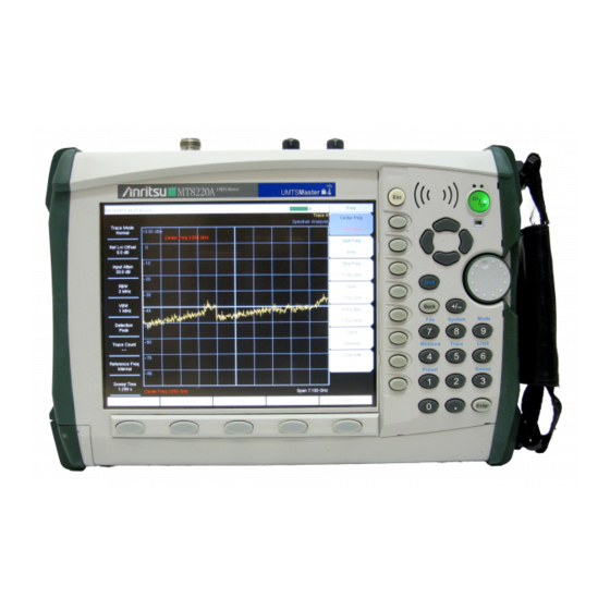
- Page 1 UMTS Master™ Model MT8220A High Performance Node B Analyzer MAINTENANCE MANUAL 490 JARVIS DRIVE P/N: 10580-00127 MORGAN HILL, CA 95037-2809 REVISION: C PRINTED: February 2008 COPYRIGHT 2007-2008 ANRITSU CO...
-
Page 3: Table Of Contents
16. ANRITSU Customer Service Centers ........ -
Page 5: Introduction
Introduction This manual provides maintenance instructions for the UMTS Master Model MT8220A Spectrum Analyzer and W- CDMA Tester. It describes the product and provides performance verification procedures, parts replacement procedures, and a replaceable parts list. Description The MT8220A is a synthesizer-based handheld spectrum analyzer and W-CDMA tester. - Page 6 Equipment Critical Specification Recommended Manufacturer/Model Synthesizer Frequency: 0.1 Hz to 20 GHz Anritsu Model MG3692A or B with options Power Output to +13 dBm 2A, 4, 22, 15 * Vector Signal Generator Frequency: 100 kHz to 3 GHz Anritsu Model MG3700A with Options...
-
Page 7: Performance Verification
The following test can be used to verify the CW frequency accuracy of the UMTS Master Spectrum Analyzer. Procedure: Connect the 10 MHz reference source to the Anritsu MG3692A Synthesized Signal Source. Do not connect the 10 MHz external reference to the MT8220A. -
Page 8: Spectrum Analyzer Internal Reference Frequency Adjustment
Press the Shift key, the Preset key (1), and then the Preset soft key to reset the instrument to the default start- ing conditions. Turn on the 10 MHz reference source and the Anritsu MG3692A Synthesized Signal Source. Set the MG3692A output to 7 GHz with an RF output level of –30 dBm. -
Page 9: Spectrum Analyzer Ssb Phase Noise Verification
Press the Shift key, the Preset key (1), and then the Preset soft key to reset to the default starting conditions. Turn on the 10 MHz reference source and the Anritsu MG3692A Synthesized Signal Source. Set the MG3692A output to 7.09 GHz CW, with an RF output level of +13 dBm. -
Page 10: Spectrum Analyzer Spurious Response (Second Harmonic Distortion)
Press the Shift key, the Preset key (1), and then the Preset soft key to reset the instrument to the default start- ing conditions. Turn on the 10 MHz reference source and the Anritsu MG3692A Synthesized Signal Source. Set the MG3692A output to 50.1 MHz CW, with an RF output level of –30 dBm. -
Page 11: Spectrum Analyzer Residual Spurious Response
Procedure: Connect the 50 Ohm termination to the UMTS Master RF Input. Connect the external power supply (Anritsu part number 40-168) to the UMTS Master. Press the On/Off key to turn on the UMTS Master. Press the Shift key, the Preset (1) key, and then the Preset soft key to reset the instrument to the default start- ing conditions. - Page 12 Procedure: Connect the 50 Ohm termination to the UMTS Master RF Input. Connect the external power supply (Anritsu part number 40-168) to the UMTS Master. Press the On/Off key to turn on the UMTS Master. Press the Shift key, the Preset (1) key, and then the Preset soft key to reset the instrument to the default start- ing conditions.
-
Page 13: Spectrum Analyzer Displayed Average Noise Level (Danl)
Procedure: Connect the 50 Ohm termination to the UMTS Master RF Input. Connect the external power supply (Anritsu part number 40-168) to the UMTS Master. Press the On/Off key to turn on the UMTS Master. Press the Shift key, the Preset (1) key, and then the Preset soft key to reset the instrument to the default start- ing conditions. -
Page 14: Input Related Spurious (Irs) Signals
Connect the 10 MHz reference source to the Anritsu MG3692A Synthesized Signal Source. Connect the output of the Anritsu MG3692A Synthesized Signal Source to the UMTS Master RF In. Set the MG3692A output to 1674 MHz, with an RF output level of –30 dBm. - Page 15 44. Record the Marker 1 amplitude reading in the test records on page 50, Amplitude Reading at 1701 MHz _______________ dBc. 45. Calculate the input related spurious level and verify that it is –50 dBm: (Input Related Spurious = Marker 1 reading – amplitude reading for 1701 MHz). UMTS Master MT8220A MM...
- Page 16 64. Record the Marker 1 amplitude reading in the test records on page 50, Amplitude Reading at 2145 MHz _______________ dBc. 65. Calculate the input related spurious level and verify that it is –60 dBm: (Input Related Spurious = Marker 1 reading – amplitude reading for 2145 MHz). UMTS Master MT8220A MM...
-
Page 17: Spectrum Analyzer Resolution Bandwidth Accuracy
Connect the 10 MHz reference source to the Anritsu MG3692A Synthesized Signal Source. Connect the output of the Anritsu MG3692A Synthesized Signal Source to the UMTS Master RF Input. Connect the external power supply (Anritsu part number 40-168) to the UMTS Master. -
Page 18: Spectrum Analyzer Measurement Accuracy
10. Repeat Steps 6 through 9 for all the frequencies in column 1 in the test records on page 51, Measuring the Unit for Frequency Level Accuracy. 11. Repeat Steps 6 through 10 for a power level of –30 dBm. UMTS Master MT8220A MM... - Page 19 NOTE: To maintain test setup integrity, do not disconnect sensor B, the power splitter or the fixed attenuator. Measuring the Unit for Frequency Level Accuracy: Remove sensor A, install the 34NN50A adapter to the end of the Attenuator, and connect to the MT8220A as shown in Figure 3.
- Page 20 Set the MG3692A output to 50 MHz CW. Connect the external power supply (Anritsu part number 40-168) to the UMTS Master. On the UMTS Master, press the Shift key, the Preset (1) key, and then the Preset soft key to reset the instru- ment to the default starting conditions.
- Page 21 18. Verify that the Marker 1 amplitude reading is within the specification in the test records on page 52, Measuring the Unit for Accuracy vs. Input Power Level. 19. Repeat Steps 12 through 18 for the other power level settings. UMTS Master MT8220A MM...
-
Page 22: Gps Option Verification (Option 31)
Do not connect the external 10 MHz Reference to the MT8220A. Connect the output of the synthesized Signal Generator to the Spectrum Analyzer RF In of the MT8220A. On the MT8220A, change the Mode to Spectrum Analyzer. Preset the unit. -
Page 23: Gsm/Gprs/Edge Signal Analyzer Option Verification (Options 40 And/Or 41)
GSM/GPRS/EDGE Signal Analyzer Option Verification (Options 40 and/or 41) The tests in this section verify the optional GSM/GPRS/EDGE Signal Analyzer functions in the MT8220A. Figure 4. GSM/GPRS/EDGE Signal Analyzer Option Verification Setup Set up Procedure: Connect the equipment as shown in Figure 4. - Page 24 27. Adjust the level of the MG3700A so that the power meter reads -10 dBm ± 0.2 dB. 28. On the MT8220A, set the Center Freq to 1800 MHz and wait 15 seconds to allow the MT8220A to update the measured results.
-
Page 25: Edge Burst Power, Frequency Error And Residual Error Tests
14. Adjust the level of the MG3700A so that the power meter reads -50 dBm ± 0.2 dB. 15. On the MT8220A, set the Center Freq to 850 MHz. Then wait 15 seconds to allow the MT8220A to update its measured results. -
Page 26: Wcdma/Hsdpa Rf Measurements (Option 44) Verification
Connect the power sensors to the power meter and calibrate the sensors. Set the mode of the MT8220A to WCDMA/HSDPA Signal Analyzer. Preset the unit. On the MG3700A, press the Preset key (yellow key on the upper left hand side). - Page 27 47. Record the measured Channel Power (dBm) reading in the +28 dBm row of the "Measured Power" column of Absolute Power Accuracy Test in the test record in Appendix A. 48. Use the following formula to calculate the absolute power accuracy of the MT8220A at +28 dBm: Error = Mea- sured Power -28...
- Page 28 57. Record the measured Channel Power (dBm) reading in the -10 dBm row of "Measured Power" column of the Absolute Power Accuracy Test in the test record. 58. Use the following formula to calculate the absolute power accuracy of the MT8220A at -10 dBm: Error = Mea- sured Power - (-10) 59.
- Page 29 Figure 6. W-CDMA Occupied Bandwidth Test Setup Ensure that the MT8220A is set to WCDMA/HSDPA Signal Analyzer mode. Preset the unit. On the MG3700A, press the Preset key (yellow key on the upper left hand side). Press the Down Arrow key to select Yes.
- Page 30 Connect the MG3700A, splitter, attenuators, power meter, and sensor to the Spectrum Analyzer RF In as shown on Figure 6. Ensure that the MT8220A is set to WCDMA/HSDPA Signal Analyzer mode. Preset the unit On the MG3700A, press the Preset key (Yellow key on the upper left hand side).
- Page 31 29. Record the calculated results in the corresponding (881.5 MHz) cells in the "Calculated ACLR Accuracy" col- umn and verify that it is within specification. 30. Repeat Steps 16 to 29 for 1962.5 MHz and 2680.5 MHz. UMTS Master MT8220A MM...
- Page 32 Connect the MG3700A, splitter, attenuators, power meter, and sensor to the Spectrum Analyzer RF In as shown on Figure 6. Ensure that the MT8220A is set to WCDMA/HSDPA Signal Analyzer mode. Preset the unit. On the MG3700A, press the Preset key (Yellow key on the upper left hand side).
-
Page 33: Error Vector Magnitude (Evm) Verification (Options 45 Or 65)
Connect the MG3700A, splitter, attenuators, power meter, and sensor to the Spectrum Analyzer RF In as shown in Figure 6. Ensure that the MT8220A is set to WCDMA/HSDPA Signal Analyzer mode. Preset the unit. On the MG3700A, press the Preset key (Yellow key on the upper left hand side). - Page 34 15. Use the knob to adjust the power meter to read -20 dBm. 16. On the MT8220A, press the Center Frequency soft key, enter 1962.5 MHz. 17. Press the Measurements soft key, then press the Demodulator soft key and select the Modulation Summary soft key.
-
Page 35: Battery Information
• Use only Anritsu approved battery packs. • Recharge the battery only in the UMTS Master or in an Anritsu approved charger. • When the UMTS Master or the charger is not in use, disconnect it from the power source. -
Page 36: Battery Pack Removal And Replacement
Place a finger in the battery access door notch and push the door down towards the bottom of the instrument, as illustrated in Figure 8. Figure 8. Battery Access Door Notch Remove the battery access door, as illustrated in Figure 9. Figure 9. Removing the Battery Access Door UMTS Master MT8220A MM... - Page 37 Replacement is the opposite of removal. Note the orientation of the battery contacts, and be sure to insert the new battery with the contacts facing the bottom of the unit, as illustrated in Figure 11. Figure 11. Battery Contacts UMTS Master MT8220A MM...
-
Page 38: Opening The Umts Master Case
Figure 13. Front Panel Assembly Removal and Cable Connections Carefully disconnect the External Reference In cable from the main PCB assembly connection marked EXT REF. Carefully disconnect the External Trigger In cable from the main PCB connection marked J3007. UMTS Master MT8220A MM... - Page 39 NOTE: Proper routing of the cables is important for instrument performance. Note the cable routing as illustrated in the drawing below. 12. Reverse the above steps to reassemble the case (Figure 14). Figure 14. Cable Routing Diagram UMTS Master MT8220A MM...
-
Page 40: Real Time Clock (Rtc) Battery Removal And Replacement
Figure 15. RTC Lithium Battery on the Main PCB Remove the battery. Place the new battery into the holder with the positive side facing up. Apply RTV to the battery and the holder to secure the battery. UMTS Master MT8220A MM... -
Page 41: Main Pcb Assembly Replacement
Pull the Main PCB assembly down and out of the Front Panel section, taking care to slide the Compact Flash module clear of the case. Replacement is the reverse of removal. Take care to insure that the connector on the Main PCB aligns with the connector on the Keypad PCB coming through the front panel. UMTS Master MT8220A MM... -
Page 42: Spectrum Analyzer Module Assembly Replacement
NOTE: There is an RF gasket material between the two halves of the case, and in the connector panel grooves. Take care not to remove or damage this material when removing or replacing the Spectrum Analyzer Module and connector panel assembly. UMTS Master MT8220A MM... -
Page 43: Lcd Assembly Replacement
Reverse the above steps to install the replacement LCD. NOTE: Pay attention to the routing of the LCD Backlight Cable. The cable must be positioned so as not to be pinched when the assembly is reattached to the front panel. UMTS Master MT8220A MM... -
Page 44: Lcd Backlight Pcb Removal And Replacement
Reverse the above steps to install the replacement LCD backlight PCB. NOTE: Pay attention to the routing of the LCD Backlight Cable. The cable must be positioned so as not to be pinched when the assembly is reattached to the front panel. UMTS Master MT8220A MM... -
Page 45: Keypad Membrane And Pcb Replacement
NOTE: The speaker is held in place by four locating pins on the inside of the keypad bezel. When the keypad bezel is removed, the speaker is held only by the fragile connecting wires. Use care not to damage the speaker wires when removing or replacing the keypad membrane or PCB. UMTS Master MT8220A MM... - Page 46 • Verify that all locking tabs are fully seated into the main body of the case when reinstalling the bezel. UMTS Master MT8220A MM...
-
Page 47: Function Key Membrane And Switchpad Replacement
Figure 25. Function Key Switchpad Reverse the above steps to install the replacement switchpad or membrane. NOTE: Carefully close the locking tab on connector J2 to secure the flexible switchpad connection. The tab should “snap” into position when fully closed. UMTS Master MT8220A MM... -
Page 48: Accessories And Replaceable Parts List
When ordering the Main/SPA PCB Assembly the options that are to be installed on the board must be defined. The options of the UMTS Master are listed on a tag at the top of the MT8220A. UMTS Master MT8220A MM... - Page 49 61363-1 Keypad Bezel, Numeric, Plastic Case 61378-1 Function Key Bezel, Plastic Case 61360-1 Encoder Knob, Plastic Case 61368 LCD Protective Cover 61381 Fan Bracket ND64383 Fan Assembly 800-473 Battery Cable, Connector 64136 ID Label, Model MT8220A UMTS Master MT8220A MM...
-
Page 50: Anritsu Customer Service Centers
16. ANRITSU Customer Service Centers For an up to date list of worldwide Anritsu Service Centers, refer to the Contact page of the Anritsu Internet site: http://www.anritsu.com/Contact.asp UMTS Master MT8220A MM... -
Page 51: Appendix A Test Records
We recommend that you make a copy of the following test record pages and document the measurements each time a Performance Verification is performed. Continuing to document this process each time it is performed provides a detailed history of the instrument’s performance. UMTS Master MT8220A MM... - Page 52 –46 dBc max (–56 dBc typical), 0 to 2800 MHz 1674 to 1774 MHz –50 dBc max (–60 dBc typical) at (Finput – 1674 MHz) 1774 to 2900 MHz –48 dBc max (–68 dBc typical) at (Finput – 1674 MHz) UMTS Master MT8220A MM...
- Page 53 – 116 dBm ≥ >2.8 GHz to 4.0 GHz 100 kHz 300 Hz _______________ dBm _______________ dBm – 126 dBm ≥ >4.0 GHz to 7.1 GHz 100 kHz 300 Hz _______________ dBm _______________ dBm – 117 dBm ≥ UMTS Master MT8220A MM...
- Page 54 330 Hz 100 Hz 150 Hz Auto 90 Hz _______________ Hz 110 Hz 30 Hz 50 Hz 3 Hz 27 Hz _______________ Hz 33 Hz 10 Hz 30 Hz 3 Hz 9 Hz _______________ Hz 11 Hz UMTS Master MT8220A MM...
- Page 55 –10 dBm _______________ dBm –14 dBm _______________ dBm –20 dBm _______________ dBm –24 dBm _______________ dBm –30 dBm _______________ dBm –34 dBm _______________ dBm –40 dBm _______________ dBm –44 dBm _______________ dBm –50 dBm _______________ dBm UMTS Master MT8220A MM...
- Page 56 –50 dBm –40 dBm 0 dB _______________ dBm ±1.25 dB Option 31 GPS Receiver Frequency Measured Value Error Specification ±4.75 Hz (w/GPS Hi Accy) or 7 GHz _______________ GHz _______________ Hz ±9.5 Hz (w/Int Hi Accy) UMTS Master MT8220A MM...
- Page 57 Measured Value Specification ≤ Burst Power Error ±1.5 dB ≤ Frequency Error ±10 Hz At 1800 MHz, -50 dBm Level, DL_MCS- 9_1SLOT Pattern Measured Value Specification ≤ Burst Power Error ±1.5 dB ≤ Frequency Error ±10 Hz UMTS Master MT8220A MM...
- Page 58 At 850 MHz, -50 dBm Level, DL_MCS-9_4SLOT Pattern Measured Value Specification ≤ EVM(rms) 2.5% At 1800 MHz, -10 dBm Level, DL_MCS-9_4SLOT Pattern Measured Value Specification ≤ EVM(rms) 2.5% At 1800 MHz, -50 dBm Level, DL_MCS-9_1SLOT Pattern Measured Value Specification ≤ EVM(rms) 2.5% UMTS Master MT8220A MM...
- Page 59 _______________ dBm _______________ 4.2 MHz ±100 kHz WCDMA RF Channel Accuracy Frequency Power Meter Measured RF RF CH Power Specification Reading Channel Power Accuracy 881.5 MHz ±1.25 dB 1962.5 MHz ±1.25 dB 2680.5 MHz ±1.25 dB UMTS Master MT8220A MM...
- Page 60 ±1.25 dB max. HSDPA ACLR Accuracy Frequency / Offset (MHz) Measured Residual ACLR Calculated ACLR Accuracy Specification 2680.5 / -10 ±1.0 dB 2680.5 / -5 ±1.0 dB 2680.5 / 5 ±1.0 dB 2680.5 / 10 ±1.0 dB UMTS Master MT8220A MM...
- Page 61 Option 45 WCDMA Demodulator and Option 65 WCDMA/HSDPA Demodulator WCDMA Error Vector Magnitude (Test Model 4; Option 45 or 65) Frequency Specification 1962.5 MHz <±2.5% HSDPA Error Vector Magnitude (Test Model 5; Option 65) Frequency Specification 1962.5 MHz <±2.5% UMTS Master MT8220A MM...
- Page 62 UMTS Master MT8220A MM...
Need help?
Do you have a question about the MT8220A and is the answer not in the manual?
Questions and answers