Table of Contents
Advertisement
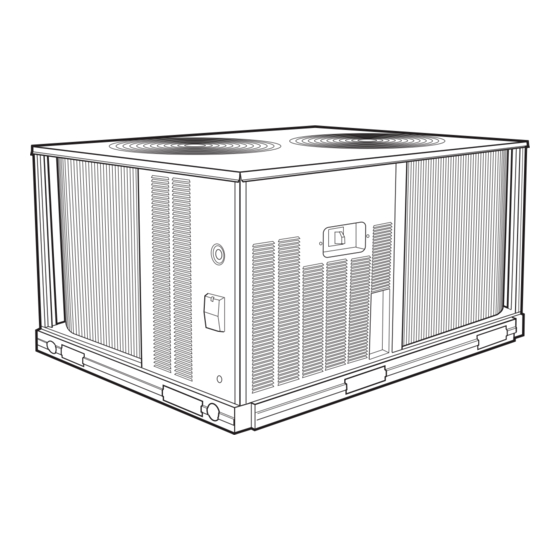
COMMERCIAL AIR-COOLED
CONDENSING UNITS WITH
524A AIR-HANDLING UNITS
FEATURES/BENEFITS
These dependable split systems match Bryant's indoor-air han-
dlers and direct-expansion coils with outdoor condensing units
for a wide selection of commercial cooling solutions.
CONSTRUCTED FOR LONG LIFE — The 569D (single cir-
cuit, scroll compressor), 576C (single circuit semi-hermetic
compressor), 569F/566E (dual circuit, scroll compressor) and
566D (semi-hermetic compressor) models are designed and
built to last. The copper tube-aluminum fin outdoor coil
construction provides years of trouble-free operation. Where
conditions require them, E-coated coils and pre-coated fin coils
are also available. Cabinets are constructed of prepainted
galvanized steel, delivering unparalleled protection from the
environment. Inside and outside surfaces are protected to
ensure long life, good looks, and reliable operation. Safety con-
trols are used for enhanced system protection and reliability.
EFFICIENT OPERATION — Building owners will appreciate
the high unit EERs (Energy Efficiency Ratios) offered by these
condensing units. These units provide greater efficiency than
similar units in the marketplace, which translates into year-
round operating savings.
CONTROLS FOR PERFORMANCE DEPENDABILITY — The
condensing units offer the building owner operating controls
and components designed for performance dependability. The
highly efficient hermetic and semi-hermetic compressors are
engineered for long life and durability. The compressors
include overload protection and vibration isolation for enhance-
ment of quiet operation. The high-pressure switch protects the
entire refrigeration system from abnormally high operating
569D072-120
576C120
569F120
Models 566D, 566E, 569D,
566D150-240
566E150-240
pressures. A low-pressure switch protects the system from
low-pressure conditions, including loss of charge.
The 569F120 and 566E150-240 units feature 2 scroll compres-
sors and 2 refrigerant circuits that provide continuous air
conditioning and design flexibility. These units also include
Cycle-LOC™ anti-short-cycling protection which helps to
protect the units against compressor failure.
All units include a crankcase heater to eliminate liquid slugging
at start-up. Units with semi-hermetic compressors are also
equipped with an oil-level sight glass.
Latest safety standards are assured through UL and UL
Canada approvals.
INNOVATIVE BRYANT PACKAGED AIR HANDLERS ARE
CUSTOM MATCHED TO THE CONDENSING UNITS — The
524A Series has excellent fan performance, efficient direct-
expansion (DX) coils, a unique combination of indoor-air qual-
ity features, and easy installation. Its versatility and state-of-
the-art features help to ensure that your split system provides
economical performance now and in the future.
Indoor-Air Quality (IAQ) Features — The unique combination
of IAQ features in the 524A Series air handlers help to ensure
that only clean, fresh, conditioned air is delivered to the occu-
pied space.
Direct-expansion (DX) cooling coils prevent the build-up of
humidity in the room, even during part-load conditions. Unit
sizes of 10 tons and above feature dual-circuit coils for
improved temperature control.
Standard 2-in. disposable filters remove dust and airborne par-
ticles from the occupied space for cleaner air.
569F, 576C
with 524A
6 to 20 Tons
524A072-300
Form No. PDS 569D.72.2
Advertisement
Table of Contents

Subscribe to Our Youtube Channel
Related Manuals for Bryant 566D


Summary of Contents for Bryant 566D
-
Page 1: Features/Benefits
569D072-120 576C120 569F120 FEATURES/BENEFITS These dependable split systems match Bryant’s indoor-air han- dlers and direct-expansion coils with outdoor condensing units for a wide selection of commercial cooling solutions. CONSTRUCTED FOR LONG LIFE — The 569D (single cir- cuit, scroll compressor), 576C (single circuit semi-hermetic... -
Page 2: Table Of Contents
Guide Specifications ......... 29-32 566D/E150-240 Model Number Nomenclature . -
Page 3: Ari Capacity Ratings
10.0 185,000 10.3 187,000 10.2 198,000 10.6 194,000 10.1 204,000 10.4 244,000 243,000 242,000 252,000 SOUND LEVELS, dB — 569D/576C/566D,E OCTAVE BANDS SOUND RATING (60 Hz) dB (A) 80.0 43.8 61.4 66.2 70.8 84.0 58.5 67.3 71.3 75.4 85.0 63.7 67.6... -
Page 4: Options And Accessories
OPTIONS Dura-Shield Condenser Coils offer several options to match coil protection to site conditions for optimum durability. See table below. Consult your Bryant representative for further information. E-Coated Aluminum-Fin Coils have a flexible and durable epoxy coating uniformly applied to all coil surfaces. Unlike brittle... - Page 5 Accessory is available unpainted or painted. Overhead Suspension Package includes necessary brackets to support units in horizontal ceiling installations. Bryant’s Line of Thermostats provide both programmable and non-programmable capability. The Commercial Electronic thermostats provide 7-day programmable capability for eco- nomical applications.
-
Page 6: Options And Accessories
DISCHARGE PLENUM RETURN-AIR GRILLE SUBBASE 524A with Discharge Plenum, Return Grille, and Subbase ECONOMIZER 524A with Economizer OPTIONS AND ACCESSORIES (cont) COIL UNIT 524A with Hot Water or Steam Coil FAN COIL UNIT HOT WATER OR STEAM COIL FAN COIL UNIT 524A with Condensate Trap... -
Page 7: Selection Procedure
To determine combination ratings for 569D/F, 576C and 566D/E units matched with 524A Series air handlers, follow these steps: I DETERMINE COOLING LOAD, TEMPERATURE, AND QUANTITY. Given: Total Cooling Capacity Required (TC)..... . 127,000 Btuh Sensible Heat Capacity Required (SHC) . -
Page 8: Operating Sequences
OPERATING SEQUENCES 569D072-120, 576C120 — At start-up, the thermostat calls for cooling. With all safety devices satisfied, the compressor contactor and fan contactor energize, causing the compressor and outdoor-fan motor to operate. Thermostat contacts energize, allowing the field-supplied and field-installed indoor- fan contactor to function. -
Page 9: Typical Wiring Schematics
NOTES: 1. If any of the original wire furnished must be replaced, it must be replaced with type 90° C wire or its equivalent. 2. Thermostat: HH07AT170, 172, 174 & P272- 2783 Subbase: HH93AZ176, 178 & P272-1882, 1883 or HH93AZ177 & 179. 3. - Page 10 LEGEND — Adjustable Heat Anticipator — Contactor, Compressor — Capacitor — Circuit Breaker — Cooling Compensator — Crankcase Heater COMP — Compressor Motor COTP — Compressor Over Temperature Protection EQUIP — Equipment — Ground — High-Pressure Switch — Indoor-Fan Contactor LLSV —...
-
Page 11: Model Number Nomenclature
569D — Commercial Air-Cooled Condensing Unit With Scroll Compressor 569F — Dual Circuit Commercial Air-Cooled Condensing Unit With Scroll Compressor Voltage Designation E — 460-3-60 P — 208/230-3-60 T — 575-3-60 Heating X — None Nominal Tons Cooling 072 — 6 (569D Only) 090 —... -
Page 12: Physical Data
UNIT NOMINAL CAPACITY (tons) OPERATING WEIGHT (lb) Aluminum Coils (Standard) Copper Coils (Optional) RREFRIGERANT TYPE* Operating Charge, Typical (lb)† Shipping Charge (lb) COMPRESSOR Type Qty...Model Oil Charge (oz) No. Cylinders Speed (rpm) CONDENSER FAN Qty...Rpm Motor HP (rpm) Diameter Nominal Airflow (Cfm Total) Watts (Total) CONDENSER COIL (Qty) Face Area (sq ft total) -
Page 13: Dimensions
ALUMINUM COIL UNIT Standard Unit Weight Corner W Corner X Corner Y Corner Z 569D072 569D090 569D120 576C120 265 120 88 DIMENSIONS Center of Gravity X mm [in.] Y mm [in.] 47 62 33 831.9 [32.75] 641.4 [25.25] 56 85 40 822.3 [32.38] 635.0 [25.00] 75 66 52 812.8 [32.00] 676.3 [26.63]... - Page 14 CORNER “A” 1162.7 [45.78] CORNER “D” ACCESS PANEL ELECTRICAL DISCONNECT O 34.5 [1.36] LOCATION POWER ENTRY WITH 50.0/58.0/65.0 K.O. CONTROL BOX ACCESS PANEL CONVENIENCE OUTLET LOCATION OUTDOOR COIL 582.5 [22.93] BOTTOM OF UNIT 167.5 [6.59] 111.7 FORK TRUCK SLOTS [4.40] (3 SIDES ONLY) O 22.0 [0.87] FIELD ENTRY SERVICE PORT...
-
Page 15: Performance Data
569D072 Air Temperature Entering Condenser (F) SST (F) 53.6 52.3 49.4 4.24 4.49 5.02 101.0 106.0 115.0 59.1 57.6 54.6 4.33 4.57 5.10 102.0 107.0 117.0 64.9 63.3 60.1 4.42 4.67 5.20 104.0 109.0 118.0 71.0 69.3 65.8 4.53 4.77 5.31 106.0 110.0... - Page 16 569D072/524A-C072 WITH HIGH-CAPACITY 4-ROW COIL Temp (F) 1800 Air Entering Condenser (Edb) 66.0 68.6 66.0 60.9 4.45 4.49 65.1 67.5 65.1 60.3 4.72 4.76 63.3 65.2 63.3 59.2 5.26 5.30 62.3 64.0 62.3 58.6 5.57 5.61 61.3 62.8 61.3 58.0 5.88 5.91 59.3...
- Page 17 569D072/524A-C090 WITH HIGH-CAPACITY 4-ROW COIL* Temp (F) 2400 Air Entering Condenser (Edb) 71.9 72.9 71.9 69.5 4.55 4.57 70.9 71.7 70.9 68.8 4.83 4.84 68.8 69.3 68.8 67.5 5.37 5.38 67.7 68.0 67.7 66.8 5.68 5.69 66.5 66.8 66.5 66.0 5.99 6.00 64.3...
- Page 18 569D090/524A-C072 WITH HIGH-CAPACITY 4-ROW COIL* Temp (F) 1800 Air Entering Condenser (Edb) 78.9 85.1 77.9 69.0 5.75 5.78 77.6 83.6 77.0 68.3 6.10 6.13 75.1 80.8 75.1 66.8 6.80 6.82 73.9 79.2 73.8 66.0 7.20 7.21 72.6 77.6 72.6 65.3 7.59 7.60 70.1...
- Page 19 569D090/524A-C090 WITH HIGH-CAPACITY 4-ROW COIL* Temp (F) 2205 Air Entering Condenser (Edb) 86.0 90.4 86.0 78.0 5.78 5.83 84.8 88.9 84.8 77.3 6.14 6.18 82.3 85.8 82.3 75.8 6.85 6.88 81.0 84.2 81.0 75.0 7.24 7.26 79.6 82.5 79.6 74.1 7.63 7.65 77.0...
- Page 20 569D120/524A-C120 WITH HIGH-CAPACITY 4-ROW COIL Temp (F) 3000 Air Entering Condenser (Edb) 117.0 122.0 117.0 106.0 8.34 8.48 115.0 120.0 115.0 104.0 8.72 8.85 112.0 116.0 112.0 102.0 9.49 9.60 110.0 113.0 110.0 101.0 9.90 10.00 108.0 111.0 108.0 100.0 10.30 10.40 104.0...
- Page 21 569D120/524A-C150 WITH HIGH-CAPACITY 4-ROW COIL Temp (F) 3750 Air Entering Condenser (Edb) 126.0 129.0 126.0 119.0 8.60 8.68 124.0 127.0 124.0 118.0 8.98 9.05 120.0 122.0 120.0 116.0 9.74 9.80 118.0 120.0 118.0 114.0 10.20 10.20 116.0 117.0 116.0 113.0 10.60 10.60 112.0...
- Page 22 576C120/524A-C120 WITH HIGH-CAPACITY 4-ROW COIL Temp (F) 3000 Air Entering Condenser (Edb) 113.0 118.0 113.0 104.0 8.00 8.12 111.0 115.0 111.0 102.0 8.39 8.51 106.0 110.0 106.0 99.8 9.17 9.28 104.0 107.0 104.0 98.4 9.55 9.65 102.0 104.0 102.0 97.0 9.93 10.00 97.2...
- Page 23 576C120/524A-C150 WITH HIGH-CAPACITY 4-ROW COIL Temp (F) 3750 Air Entering Condenser (Edb) 122.0 125.0 122.0 117.0 8.23 8.28 120.0 122.0 120.0 116.0 8.64 8.69 115.0 116.0 115.0 113.0 9.46 9.50 113.0 113.0 113.0 111.0 9.86 9.89 110.0 111.0 110.0 109.0 10.30 10.30 105.0...
- Page 24 569F120/524A-C120 WITH HIGH-CAPACITY 4-ROW COIL Temp (F) 3000 Air Entering Condenser (Edb) 112.0 116.0 112.0 102.0 7.90 7.94 110.0 114.0 110.0 102.0 8.35 8.39 107.0 110.0 107.0 99.6 9.24 9.28 105.0 108.0 105.0 98.6 9.74 9.78 103.0 106.0 103.0 97.5 10.20 10.30 99.7...
-
Page 25: Performance Data
569F120/524A-C150 WITH HIGH-CAPACITY 4-ROW COIL Temp (F) 3750 Air Entering Condenser (Edb) 121.0 123.0 121.0 116.0 8.00 8.03 119.0 121.0 119.0 115.0 8.45 8.48 115.0 117.0 115.0 112.0 9.35 9.37 113.0 115.0 113.0 111.0 9.86 9.87 112.0 113.0 112.0 110.0 10.40 10.40 108.0... -
Page 26: Electrical Data
FACTORY- UNIT INSTALLED SIZE OPTION NONE OR DISCONNECT CONVENIENCE OUTLET NONE OR DISCONNECT CONVENIENCE OUTLET NONE OR DISCONNECT CONVENIENCE OUTLET NONE OR DISCONNECT CONVENIENCE OUTLET NONE OR DISCONNECT 569D CONVENIENCE OUTLET NONE OR DISCONNECT CONVENIENCE OUTLET NONE OR DISCONNECT CONVENIENCE OUTLET NONE OR DISCONNECT CONVENIENCE OUTLET NONE OR DISCONNECT... -
Page 27: Application Data
APPLICATION DATA — 569D072-120, 576C090-120, 569F120 OPERATING LIMITS Maximum Cooling Outdoor 115 F See Minimum Outdoor-Air Minimum Outdoor Ambient Operating Temperature table at right. Minimum Return-Air 55 F Temperature Maximum Return-Air 95 F Temperature Normal Acceptable Saturation 25 to 55 F Suction Temperature Range Maximum Discharge 275 F... -
Page 28: Typical Piping And Wiring
WEATHERPROOF FUSED DISCONNECT* PER NEC FIELD SUPPLIED POWER POWER WIRES INSULATED VAPOR LINE CONTROL WIRES INDOOR THERMOSTAT† LEGEND LLSV — Liquid Line Solenoid Valve NEC — National Electrical Code — Thermostatic Expansion Valve *Field supplied. †Accessory item. Rooftop Installation — 569D072-120, 576C120 TYPICAL PIPING AND WIRING CONDENSING MOISTURE... -
Page 29: Guide Specifications
GUIDE SPECIFICATIONS — 569D072-120, 576C120 COMMERCIAL AIR-COOLED CONDENSING UNITS HVAC GUIDE SPECIFICATIONS SIZE RANGE: 6 TO 10 TONS, NOMINAL BRYANT MODEL NUMBERS: 569D, SIZES 072-120 576C, SIZE 120 PART 1 — GENERAL 1.01 SYSTEM DESCRIPTION Outdoor-mounted, air-cooled condensing unit suitable for on-the-ground or rooftop installation. - Page 30 GUIDE SPECIFICATIONS — 569D072-120, 576C120 (cont) J. Special Features: 1. Low-Ambient Temperature Control Accessory: Low-ambient control shall be available as a factory- installed option or a field-installed accessory and shall regulate speed of condenser-fan motor in response to the saturated condensing temperature of the unit.
-
Page 31: Guide Specifications
COMMERCIAL AIR-COOLED CONDENSING UNITS HVAC GUIDE SPECIFICATIONS SIZE RANGE: 10 TONS, NOMINAL BRYANT MODEL NUMBER: 569F, SIZE 120 PART 1 — GENERAL 1.01 SYSTEM DESCRIPTION Outdoor-mounted, air-cooled condensing unit suitable for on-the-ground or rooftop installation. Unit shall have 2 independent refrigeration circuits. Unit shall consist of dual scroll compressors, air-cooled coils, propeller-type condenser fans, and a control box. -
Page 32: Guide Specifications
GUIDE SPECIFICATIONS — 569F120 (cont) 3. Optional Condenser Coil Materials: a. Pre-Coated Aluminum-Fin Coils: Shall have a durable epoxy-phenolic coating to provide protection in mildly corrosive coastal environments. Coating shall be applied to the aluminum fin stock prior to the fin stamping process to create an inert barrier between the aluminum fin and copper tube. -
Page 33: Model Number Nomenclature
566D — Commercial Air-Cooled Condensing Unit With Semi-Hermetic Compressor 566E — Dual Circuit Commercial Air-Cooled Condensing Unit With Scroll Compressors Voltage Designation E — 460-3-60 P — 208/230-3-60 T — 575-3-60 Heating X — None *Contact your local representative for more details. -
Page 34: Physical Data
UNIT NOMINAL CAPACITY (tons) OPERATING WEIGHTS (lb) Aluminum-Fin Coil (Standard) Copper-Fin Coil (Optional) REFRIGERANT TYPE* Operating Charge, Typical (lb)† Shipping Charge (lb) COMPRESSOR Qty...Model No. Cylinders Speed (rpm) Oil Charge (pt) Capacity Steps Accessory Standard Unloader Setting (psig) Load Unload Crankcase Heater Watts CONDENSER FANS Qty...Rpm... - Page 35 PHYSICAL DATA (cont) 566E150-240 UNITS UNIT NOMINAL CAPACITY (tons) OPERATING WEIGHTS (lb) Aluminum-Fin Coil (Standard) Copper-Fin Coil (Optional) REFRIGERANT TYPE* Operating Charge, Typical (lb)† Shipping Charge (lb) COMPRESSOR Qty...Model Speed (rpm) Oil Charge (oz) Crankcase Heater Watts CONDENSER FANS Qty...Rpm Diameter (in.) Nominal Hp Nominal Airflow (cfm, total)
-
Page 36: Dimensions
NOTES: 1. Service clearances are as follows: Side (compressor) — 3 Side (opposite compressor) — 3 ft Ends — 2 ft Top — 5 ft 2. See page 38 for corner weights and unit center of gravity. DIMENSIONS 566D150-240... - Page 37 NOTES: 1. Service clearances are as follows: Side (compressor) — 3 ft (1067 mm) Side (opposite compressor) — 3 ft (914 mm) Ends — 2 ft (610 mm) Top — 5 ft (1524 mm) 2. See page 38 for corner weights and unit center of gravity.
-
Page 38: Dimensions
UNIT 566D UNIT 566E NOTES: 1. Corner weights are approximate. 2. Actual support weights depend on level of unit and evenness of support posts. 3. Total weights represent approximate unit weights without shipping package. 4. Bottom or top skid is NOT included in the weights. -
Page 39: Performance Data
566D150 Air Temperature Entering Condenser (F) SST (F) 101.0 97.6 90.0 8.56 8.90 9.55 94.6 99.4 109.0 118.0 113.0 105.0 8.80 9.17 9.90 96.6 101.0 111.0 134.0 129.0 120.0 9.03 9.44 10.20 98.6 103.0 113.0 150.0 145.0 135.0 9.26 9.71 10.60 101.0 105.0... - Page 40 566D150/524A-C150 WITH HIGH CAPACITY 4-ROW COIL Temp (F) 3750 Air Entering Condenser (Edb) 133.0 139.0 133.0 123.0 9.00 9.07 131.0 136.0 131.0 122.0 9.44 9.54 126.0 130.0 126.0 119.0 10.40 10.50 123.0 127.0 123.0 117.0 10.80 10.90 121.0 124.0 121.0 116.0 11.30 11.40...
- Page 41 566D150/524A-C180 WITH HIGH CAPACITY 4-ROW COIL Temp (F) 4500 Air Entering Condenser (Edb) 142.0 145.0 142.0 136.0 9.13 9.17 140.0 142.0 140.0 134.0 9.60 9.65 134.0 136.0 134.0 131.0 10.50 10.60 132.0 133.0 132.0 129.0 11.00 11.10 129.0 130.0 129.0 127.0 11.50 11.50...
- Page 42 566D180/524A-C180 WITH HIGH-CAPACITY 4-ROW COIL Temp (F) 4500 Air Entering Condenser (Edb) 167.0 177.0 167.0 152.0 13.10 13.40 165.0 174.0 165.0 150.0 13.70 14.00 160.0 167.0 160.0 147.0 14.90 15.20 157.0 164.0 157.0 145.0 15.50 15.80 154.0 160.0 154.0 144.0 16.00 16.30 148.0...
- Page 43 566D180/524A-C240 WITH HIGH-CAPACITY 4-ROW COIL Temp (F) 6,000 Air Entering Condenser (Edb) 196.0 200.0 196.0 188.0 13.90 14.00 193.0 196.0 193.0 186.0 14.60 14.70 186.0 188.0 186.0 182.0 15.90 16.00 183.0 184.0 183.0 179.0 16.50 16.60 179.0 180.0 179.0 177.0 17.20 17.20 172.0...
- Page 44 566D240/524A-C300 WITH HIGH-CAPACITY 4-ROW COIL Temp (F) 7,500 Air Entering Condenser (Edb) 244.0 249.0 244.0 233.0 18.90 19.20 239.0 244.0 239.0 231.0 19.70 19.90 230.0 233.0 230.0 225.0 21.30 21.40 226.0 228.0 226.0 222.0 22.00 22.10 221.0 222.0 221.0 219.0 22.80 22.80 212.0...
- Page 45 566E150/524A-C120 WITH HIGH-CAPACITY 4-ROW COIL Temp (F) 3000 Air Entering Condenser (Edb) 126.0 135.0 126.0 112.0 9.13 9.18 125.0 133.0 125.0 111.0 9.68 9.72 121.0 129.0 121.0 109.0 10.90 11.00 119.0 127.0 119.0 108.0 11.60 11.60 118.0 124.0 118.0 107.0 12.30 12.30 114.0...
- Page 46 566E150/524A-C150 WITH HIGH-CAPACITY 4-ROW COIL Temp (F) 3750 Air Entering Condenser (Edb) 139.0 145.0 139.0 127.0 9.18 9.21 137.0 143.0 137.0 126.0 9.74 9.76 133.0 138.0 133.0 124.0 11.00 11.00 131.0 136.0 131.0 123.0 11.60 11.60 129.0 133.0 129.0 121.0 12.30 12.30 125.0...
- Page 47 566E150/524A-C180 WITH HIGH-CAPACITY 4-ROW COIL Temp (F) 4500 Air Entering Condenser (Edb) 152.0 156.0 152.0 145.0 9.24 9.26 150.0 154.0 150.0 144.0 9.80 9.82 146.0 148.0 146.0 141.0 11.00 11.10 144.0 146.0 144.0 140.0 11.70 11.70 141.0 143.0 141.0 138.0 12.40 12.40 137.0...
- Page 48 566E180/524A-C150 WITH HIGH-CAPACITY 4-ROW COIL Temp (F) 3750 Air Entering Condenser (Edb) 163.0 175.0 161.0 142.0 12.60 12.80 160.0 172.0 159.0 141.0 13.10 13.40 155.0 166.0 155.0 138.0 14.30 14.60 152.0 163.0 152.0 136.0 14.90 15.20 150.0 159.0 150.0 134.0 15.60 15.80 144.0...
- Page 49 566E180/524A-C180 WITH HIGH-CAPACITY 4-ROW COIL Temp (F) 4500 Air Entering Condenser (Edb) 180.0 190.0 180.0 162.0 12.90 13.20 177.0 187.0 177.0 160.0 13.50 13.80 172.0 180.0 172.0 157.0 14.70 14.90 169.0 176.0 169.0 155.0 15.40 15.60 166.0 172.0 166.0 153.0 16.00 16.20 159.0...
- Page 50 566E180/524A-C240 WITH HIGH-CAPACITY 4-ROW COIL Temp (F) 6,000 Air Entering Condenser (Edb) 201.0 205.0 201.0 191.0 13.40 13.50 198.0 202.0 198.0 190.0 14.00 14.10 191.0 194.0 191.0 186.0 15.30 15.30 188.0 190.0 188.0 183.0 15.90 15.90 184.0 185.0 184.0 181.0 16.50 16.60 176.0...
- Page 51 566E240/524A-C240 WITH HIGH-CAPACITY 4-ROW COIL Temp (F) 6,000 Air Entering Condenser (Edb) 228.0 239.0 228.0 207.0 17.60 18.00 225.0 235.0 225.0 205.0 18.40 18.70 218.0 227.0 218.0 201.0 20.00 20.30 214.0 222.0 214.0 199.0 20.90 21.10 211.0 217.0 211.0 196.0 21.70 22.00 203.0...
-
Page 52: Performance Data
566E240/524A-C300 WITH HIGH-CAPACITY 4-ROW COIL Temp (F) 7,500 Air Entering Condenser (Edb) 249.0 254.0 249.0 236.0 18.30 18.50 245.0 249.0 245.0 234.0 19.10 19.20 237.0 240.0 237.0 229.0 20.70 20.80 232.0 235.0 232.0 226.0 21.50 21.60 228.0 230.0 228.0 223.0 22.30 22.40 219.0... -
Page 53: Electrical Data
NOMINAL UNIT VOLTAGE SIZE (3-Ph, 60 Hz) 208/230 208/230 566D 208/230 LEGEND — Full Load Amps HACR — Heating, Air Conditioning and Refrigeration — Maximum Instantaneous Current Flow During Start-Up (LRA of compressor plus total FLA of fan motors) — Total Fan Motor Input (kilowatts) —... -
Page 54: Operating Limits
Maximum Discharge 295 F Temperature Minimum Discharge Superheat 60 F MINIMUM OUTDOOR-AIR OPERATING TEMPERATURE — 566D150-240 UNITS FULL LOAD UNIT NO. OF CAPACITY 566D CYLINDERS *Requires field-installed unloader. LIQUID LINE LIQUID LINE UNIT SIZE (in.) SOLENOID VALVE (LLSV) 200RB7T4M 566D150 200RA8T5M... - Page 55 Valve Serving 2 Coil Circuits (Solenoid Drop Control) TXV — Thermostatic Face-Split Coil Suction and Liquid Line Piping LINEAR LENGTH OF INTERCONNECTING PIPING (FT) 0-15 UNIT 566D LINEAR LENGTH OF INTERCONNECTING PIPING (FT) 0-25 UNIT 566E LEGEND L — Liquid S — Suction Close-coupled.
-
Page 56: Application Data
APPLICATION DATA — 566D150-240, 566E150-240 (cont) MULTIPLE CONDENSING UNIT ARRANGEMENTS* 566D, 566E150-240 566D, 566E150-240 566D, 566E150-240 Space for Service and Airflow *For clearances between controls and grounded surfaces, check local codes. 566D,566E DIMENSIONS (ft) 150-240... -
Page 57: Typical Piping And Wiring
LEGEND NEC — National Electrical Code TXV — Thermostatic Expansion Valve Piping *Field supplied. TYPICAL PIPING AND WIRING NOTES: 1. All piping must follow standard refrigerant piping techniques. 2. All wiring must comply with the applicable local and national codes. 3. - Page 58 LEGEND NEC — National Electrical Code TXV — Thermostatic Expansion Valve Piping *Field supplied. TYPICAL PIPING AND WIRING (cont) NOTES: 1. All piping must follow standard refrigerant piping techniques. 2. All wiring must comply with the applicable local and national codes.
-
Page 59: Guide Specifications
Copper fins shall be available as an option. F. Refrigeration Components: manufacturer’s 1. Refrigeration circuit components for 566D units shall include hot gas muffler, high-side pressure relief device, liquid line shutoff valve, suction and dis- charge shutoff valves, holding charge of refrigerant R-22, and compressor oil. - Page 60 GUIDE SPECIFICATIONS — 566D150-240, 566E150-240 (cont) Manual reset at the unit Electrical overload protection through the use of def- inite-purpose contactors and calibrated, ambient compensated, magnetic trip circuit breakers. Circuit breakers shall open all 3 phases in the event of an overload in any one of the phases or a single-phase condition.
-
Page 61: Model Number Nomenclature
524A — Fan Coil Voltage E — 460-3-60† J — 208/230-1-60 (Sizes 072, 090 Only) P — 208/230-3-60 T — 575-3-60 Coil Option B — DX Cooling Coil With TXVs C — DX High Capacity Cooling Coil With TXVs Nominal Cooling (Tons) 072 —... -
Page 62: Physical Data
UNIT 524A NOMINAL CAPACITY (Tons) OPERATING WEIGHT (lb) Base Unit with TXV (3 Row/4 Row) Plenum Economizer Hot Water Coil Steam Coil FANS Qty...Diam. (in.) Nominal Airflow (cfm) Airflow Range (cfm) Nominal Motor Hp (Standard Motor)* 208/230-1-60 208/230-3-60 and 460-3-60 575-3-60 Motor Speed (rpm) 208/230-1-60... -
Page 63: Dimensions
• Front: 2′-6″ (762 mm) • Right Side: 2′-6″ (762 mm) • Left Side: 2′-6″ (762 mm) • Local codes or jurisdiction may prevail. 4. Liquid piping not supplied by Bryant. 5. Duct flange is factory supplied and field installed. 524A-B,C072-120... - Page 64 • Front: 2′-6″ (762 mm) • Right Side: 2′-6″ (762 mm) • Left Side: 2′-6″ (762 mm) • Local codes or jurisdiction may prevail. 4. Liquid piping not supplied by Bryant. 5. Duct flange is factory supplied and field installed. 524A-B,C150-240...
-
Page 65: Dimensions
• Front: 2′-6″ (762 mm) • Right Side: 2′-6″ (762 mm) • Left Side: 2′-6″ (762 mm) • Local codes or jurisdiction may prevail. 4. Liquid piping not supplied by Bryant. 5. Duct flange is factory supplied and field installed. UNIT... -
Page 66: Performance Data
524A-B FAN PERFORMANCE DATA — 0.0-1.2 in. wg ESP UNIT AIRFLOW 524A-B (Cfm) 1,800 0.19 2,100 0.28 2,400 0.40 2,700 0.55 3,000 0.73 2,250 0.08 2,600 0.15 3,000 0.65 3,400 0.91 3,750 1.20 3,000 0.29 3,500 0.92 4,000 1.33 4,500 1.86 5,000 2.51... - Page 67 524A-B FAN PERFORMANCE DATA — 1.4-2.4 in. wg ESP UNIT AIRFLOW 524A-B (Cfm) 1,800 1.04 2,100 1.21 2,400 1.41 2,700 1.63 3,000 1.89 2,250 1.26 2,600 1.48 3,000 1.79 3,400 2.18 3,750 1360 2.58 3,000 1.74 3,500 2.21 4,000 1040 2.80 4,500 1094...
- Page 68 FAN PERFORMANCE DATA — 524A-C WITH HIGH CAPACITY COIL — UNIT 524A-C AIRFLOW (High-Capacity (Cfm) 4-Row Coil) 1,800 2,100 2,400 2,700 3,000 2,250 2,600 3,000 3,400 3,750 3,000 3,500 4,000 4,500 5,000 3,750 4,300 5,000 5,700 6,250 4,500 5,300 6,000 6,800 7,500 6,000...
- Page 69 UNIT 524A-C AIRFLOW (High-Capacity (Cfm) 4-Row Coil) 1,800 2,100 2,400 2,700 3,000 1015 2,250 2,600 3,000 3,400 1018 3,750 1057 3,000 3,500 1005 4,000 1058 4,500 1116 5,000 1176 3,750 4,300 5,000 5,700 6,250 1019 4,500 5,300 6,000 6,800 1005 7,500 1036 6,000...
- Page 70 FACTORY-SUPPLIED FILTER PRESSURE DROP UNIT AIRFLOW PRESSURE DROP 524A-B (Cfm) 524A-C 1,800 2,400 3,000 2,250 3,000 3,750 3,000 4,000 5,000 3,750 5,000 6,250 4,500 6,000 7,500 6,000 8,000 10,000 7,500 10,000 12,500 UNIT AIRFLOW DISCHARGE 524A (Cfm) PLENUM 1,800 0.06 2,400 0.10 3,000...
-
Page 71: Performance Data
UNIT AIRFLOW 524A-B (Cfm) 524A-C 1,800 2,400 3,000 2,250 3,000 3,750 3,000 4,000 5,000 3,750 5,000 6,250 4,500 6,000 7,500 6,000 8,000 10,000 7,500 10,000 12,500 LEGEND Cap. — Capacity (Btuh in thousands) Lab — Leaving-Air Dry-Bulb Temp (F) — Pressure Drop (ft water) *Based on 5 psig steam, 60 F entering-air temperature. -
Page 72: Electrical Data
UNIT 524A-B V*-PH-Hz 524A-C 208/230-1-60 208/230-3-60 460-3-60 575-3-60 208/230-1-60 208/230-3-60 460-3-60 575-3-60 208/230-3-60 460-3-60 575-3-60 208/230-3-60 460-3-60 575-3-60 208/230-3-60 460-3-60 575-3-60 208/230-3-60 460-3-60 575-3-60 208/230-3-60 460-3-60 575-3-60 See Legend and Notes on page 73. ELECTRICAL DATA 524A-B,C STANDARD MOTORS FAN MOTOR VOLTAGE LIMITS Hp (kW) - Page 73 UNIT 524A-B V*-PH-Hz 524A-C 208/230-1-60 208/230-3-60 460-3-60 575-3-60 208/230-1-60 208/230-3-60 460-3-60 575-3-60 208/230-3-60 460-3-60 575-3-60 208/230-3-60 460-3-60 575-3-60 208/230-3-60 460-3-60 575-3-60 208/230-3-60 460-3-60 575-3-60 208/230-3-60 460-3-60 575-3-60 LEGEND — Full Load Amps MOCP — Maximum Overcurrent Protection *Motors are designed for satisfactory operation within 10% of nominal voltages shown.
-
Page 74: Electric Heater(S)
HEATER PART NO. UNIT CAELHEAT001A00 CAELHEAT002A00 CAELHEAT003A00 CAELHEAT004A00 524A-B072-120 524A-C072-120 CAELHEAT005A00 CAELHEAT006A00 CAELHEAT007A00 CAELHEAT008A00 CAELHEAT009A00 See Legend and Notes on page 75. ELECTRICAL DATA (cont) ELECTRIC HEATER DATA FAN MOTOR V-PH-Hz Nominal Capacity (kW) 1.3† 0.97 2.4† 1.79 11.0 208-3-60 1.79 2.16 2.76... - Page 75 HEATER PART NO. UNIT CAELHEAT010A00 CAELHEAT011A00 524A-B072-120 CAELHEAT012A00 524A-C072-120 CAELHEAT013A00 CAELHEAT014A00 CAELHEAT015A00 LEGEND — Full Load Amps — Horsepower — Minimum Circuit Amps MOCP — Maximum Overcurrent Protection (Amps) *Values shown are for single-point connection of electric heat acces- sory and air handler. †Single-phase motors.
- Page 76 HEATER PART NO. UNIT V-PH-Hz 208-3-60 CAELHEAT016A00 240-3-60 CAELHEAT017A00 480-3-60 CAELHEAT018A00 575-3-60 208-3-60 CAELHEAT019A00 240-3-60 524A-B150-240 524A-C150-240 CAELHEAT020A00 480-3-60 CAELHEAT021A00 575-3-60 208-3-60 CAELHEAT022A00 240-3-60 CAELHEAT023A00 480-3-60 CAELHEAT024A00 575-3-60 See Legend and Notes on page 77. ELECTRICAL DATA (cont) ELECTRIC HEATER DATA (cont) ELECTRIC HEATER(S) FAN MOTOR Actual Capacity (kW)
- Page 77 HEATER PART NO. UNIT CAELHEAT025A00 524A-B180,240 524A-C180,240 CAELHEAT026A00 CAELHEAT027A00 CAELHEAT028A00 CAELHEAT029A00 CAELHEAT030A00 524A-B300 524A-C300 CAELHEAT031A00 CAELHEAT032A00 CAELHEAT033A00 LEGEND — Full Load Amps — Horsepower MCA — Minimum Circuit Amps MOCP— Maximum Overcurrent Protection (Amps) *Values shown are for single-point connection of electric heat acces- sory and air handler.
-
Page 78: Electrical Data
HEATER PART NO. UNIT V-PH-Hz 208-3-60 CAELHEAT034A00 240-3-60 CAELHEAT035A00 480-3-60 CAELHEAT036A00 575-3-60 524A-B300 524A-C300 208-3-60 CAELHEAT037A00 240-3-60 CAELHEAT038A00 480-3-60 CAELHEAT039A00 575-3-60 LEGEND — Full Load Amps — Horsepower MCA — Minimum Circuit Amps MOCP — Maximum Overcurrent Protection (Amps) *Values shown are for single-point connection of electric heat acces- sory and air handler. -
Page 79: Application Data
1. OPERATING LIMITS Maximum fan speed — 524A-B,C072-240 ..1200 rpm Maximum fan speed — 524A-B,C300 . . . 1100 rpm (18.3 r/s) 2. GENERAL — Select equipment to match or to be slightly less than peak load. - Page 80 UNIT SIZE 524A 208/230-1-60 Speed (rpm) Frame (NEMA) Shaft Dia (in.) 230-3-60 and 460-3-60 Speed (rpm) Frame (NEMA) Shaft Dia (in.) 575-3-60 Speed (rpm) Frame (NEMA) Shaft Dia (in.) LEGEND NEMA — National Electrical Manufacturers Association UNIT SIZE 524A MOTOR DRIVE Motor Pulley Pitch Diameter (in.) Pulley Factory Setting Full Turns Open...
-
Page 81: Application Data
UNIT SIZE 524A MOTOR DRIVE Motor Pulley Pitch Diameter (in.) Pulley Factory Setting Full Turns Open FAN DRIVE Pulley Pitch Dia (in.) Pulley Bore (in.) Belt No. — Section Belt Pitch (in.) FAN SPEEDS (rpm) Factory Setting Range Max Allowable Speed (rpm) Change per Turn of Moveable Motor Pulley... -
Page 82: Guide Specifications
COMMERCIAL PACKAGED AIR-HANDLING UNIT HVAC GUIDE SPECIFICATIONS SIZE RANGE: 1,800 to 12,500 CFM, NOMINAL AIRFLOW 6 TO 25 TONS, NOMINAL COOLING BRYANT MODEL NUMBERS: 524A-B (DIRECT-EXPANSION COIL), 524A-C (HIGH-CAPACITY 4-ROW DIRECT-EXPANSION COIL) PART 1 — GENERAL 1.01 SYSTEM DESCRIPTION A. Indoor, packaged air-handling unit for use in commercial split systems. -
Page 83: Guide Specifications
GUIDE SPECIFICATIONS — 524A (cont) 5. Electric Heaters: Heaters for nominal 240, 480, or 575-volt, 3-phase, 60 Hz power supply shall be factory-supplied for field installation as shown on the equipment drawings. Electric heat assembly shall be ETL and ETL, Can- ada, agency approved, and shall have single-point power wiring. - Page 84 Minimum ambient operating temperature 27, 54 Minimum temperature 27, 54 Model number nomenclature 569D/E072-120, 576C120 566D/E150-240 524A072-300 Copyright 2004 Bryant Heating & Cooling Systems INDEX Motormaster® options Operating sequence Options and accessories 569D/F, 576C, 566D/E 524A 5, 6 Performance data...
Need help?
Do you have a question about the 566D and is the answer not in the manual?
Questions and answers