
Related Manuals for Vega VEGATOR 122


Summary of Contents for Vega VEGATOR 122
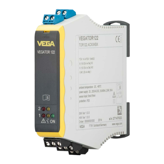
- Page 1 Operating Instructions Double channel controller for level detection for 8/16 mA sensors VEGATOR 122 Document ID: 46108...
-
Page 2: Table Of Contents
Approvals for Ex areas ....................23 EU conformity ......................... 23 SIL conformity (optional) ....................23 Environment management system ................. 23 10 Supplement ..........................24 10.1 Technical data ........................ 24 10.2 Dimensions ........................26 10.3 Industrial property rights ....................27 VEGATOR 122 •... - Page 3 Contents 10.4 Trademark ........................27 Supplementary documentation Information: Supplementary documents appropriate to the ordered version come with the delivery. You can find them listed in chapter " Product descrip- tion". Editing status: 2021-07-12 VEGATOR 122 •...
-
Page 4: About This Document
Symbols used Document ID This symbol on the front page of this instruction refers to the Docu- ment ID. By entering the Document ID on www.vega.com you will reach the document download. Information, note, tip: This symbol indicates helpful additional infor- mation and tips for successful work. -
Page 5: For Your Safety
During work on and with the device, the required personal protective equipment must always be worn. Appropriate use VEGATOR 122 is a universal controller for connection of level switches. You can find detailed information about the area of application in chapter " Product description". Operational reliability is ensured only if the instrument is properly used according to the specifications in the operating instructions manual as well as possible supplementary instructions. -
Page 6: Safety Instructions For Ex Areas
Canadian Electrical Code. Safety instructions for Ex areas For applications in explosion-proof areas (Ex), only devices with cor- responding Ex approval may be used. Observe the Ex-specific safety instructions. These are an integral part of the operating instructions and are enclosed with every device with Ex approval. VEGATOR 122 •... -
Page 7: Product Description
Principle of operation Application area The VEGATOR 122 is a double-channel controller for level detection with two level switches with 8/16 mA interface. Simple monitoring and control functions can be realised via the integrated relays. Typical applications are monitoring functions such as overfill and dry run protection. -
Page 8: Adjustment
• Protected against solar radiation • Avoiding mechanical shock and vibration • Storage and transport Storage and transport temperature see chapter " Supplement - temperature Technical data - Ambient conditions" • Relative humidity 20 … 85 % VEGATOR 122 •... -
Page 9: Mounting
Mounting General instructions Mounting options VEGATOR 122 is designed for carrier rail mounting (top hat rail 35 x 7.5 according to DIN EN 50022/60715). Due to its protection rating of IP20, the instrument is suitable for mounting in switching cabinets. It can be mounted horizontally and vertically. -
Page 10: Connecting To Power Supply
Voltage supply The data for power supply are specified in chapter " Technical data". Connection cable The voltage supply of VEGATOR 122 is connected with standard cable according to the national installation standards. The sensors are connected with standard two-wire cable without shielding. If electromagnetic interference is expected which is above the test values of EN 61326 for industrial areas, shielded cable should be used. -
Page 11: Connection Procedure
2. Connect sensor cable 1 to terminal 1/2, and where applicable, connect the shielding 3. Connect sensor cable 2 to terminal 4/5, and where applicable, connect the shielding 4. Connect switched-off power supply to terminal 16/17 5. Connect relay 1 to terminal 10/11/12 6. Connect relay 2 to terminal 13/14/15 The electrical connection is finished. VEGATOR 122 •... -
Page 12: Wiring Plan
Sensor circuit, channel 2 (8/16 mA), min. level with two-point control Relay output channel 1 Relay output channel 2 Voltage supply Information: The connection terminals can be detached towards the front, if necessary. This can be useful when working in tight spaces or when exchanging an instrument. VEGATOR 122 •... -
Page 13: Setup
Green – Operating control lamp – Mains voltage on, instrument is operating • – Fault indicator – Fault on the sensor circuit due to sensor failure or line break – The relay deenergises in case of failure VEGATOR 122 •... - Page 14 If the connected sensor has an own mode switch, then this switch must be set to " Max.". Switch-on pulse monitor- While switching on, the sensors VEGASWING, VEGAVIB, VEGA- WAVE deliver a defined switching sequence in which the switching conditions empty/full/failure are run through. This switching sequence VEGATOR 122 •...
- Page 15 VEGATOR 122 displays a fault. A function test is only triggered by pressing the test key. This function test is not carried out automatically when switching on the VEGATOR 122.
-
Page 16: Function Table "Point Level
(fault) approx. 8 mA approx. 16 mA < 3.6 mA > 21 mA Dry run protection, point level Sensor Controller Level Sensor cur- LED yellow LED red Relay rent (output) (fault) approx. 16 mA approx. 8 mA VEGATOR 122 •... -
Page 17: Function Table, Two-Point Control
(fault) approx. 8 mA approx. 8 mA approx. 8 mA approx. 16 mA approx. 16 mA approx. 16 mA approx. 8 mA approx. 16 mA approx. 8 mA approx. 8 mA < 3.6 mA > 21 mA VEGATOR 122 •... - Page 18 (fault) approx. 8 mA approx. 8 mA approx. 8 mA approx. 16 mA approx. 16 mA approx. 16 mA approx. 8 mA approx. 16 mA approx. 8 mA approx. 8 mA < 3.6 mA > 21 mA VEGATOR 122 •...
-
Page 19: Diagnostics And Servicing
Should these measures not be successful, please call in urgent cases 24 hour service hotline the VEGA service hotline under the phone no. +49 1805 858550. The hotline is also available outside normal working hours, seven days a week around the clock. -
Page 20: How To Proceed If A Repair Is Necessary
By doing this you help us carry out the repair quickly and without having to call back for needed information. In case of repair, proceed as follows: VEGATOR 122 •... - Page 21 Clean the instrument and pack it damage-proof • Attach the completed form and, if need be, also a safety data sheet outside on the packaging • Ask the agency serving you to get the address for the return ship- ment. You can find the agency on our homepage. VEGATOR 122 •...
-
Page 22: Dismount
Disposal The device is made of recyclable materials. For this reason, it should be disposed of by a specialist recycling company. Observe the ap- plicable national regulations. VEGATOR 122 •... -
Page 23: Certificates And Approvals
That is why we have introduced an environment management system with the goal of continuously improving company environmental pro- tection. The environment management system is certified according to DIN EN ISO 14001. Please help us fulfil this obligation by observ- ing the environmental instructions in chapters " Packaging, transport and storage", " Disposal" of these operating instructions. VEGATOR 122 •... -
Page 24: Supplement
24 … 65 V (-15 %, +10 %) Max. power consumption 3 W (8 VA) Sensor input Quantity 2 x analogue Input type Active (sensor power supply by VEGATOR 122) Measured value transmission Analogue 8/16 mA Switching threshold Ʋ On 12.1 mA Ʋ Off 11.9 mA... - Page 25 Ʋ Insulation resistance 5.1 kV If inductive loads or stronger currents are switched through, the gold plating on the relay contact surface will be permanently damaged. The contact is then no longer suitable for switching low-level signal circuits. VEGATOR 122 •...
-
Page 26: Dimensions
For that reason the associated approval documents of these instruments have to be carefully noted. They are part of the delivery or can be downloaded by entering the serial number of your instrument into the search field under www.vega.com as well as in the general download area. 10.2 Dimensions... -
Page 27: Industrial Property Rights
Les lignes de produits VEGA sont globalement protégées par des droits de propriété intellec- tuelle. Pour plus d'informations, on pourra se référer au site www.vega.com. VEGA lineas de productos están protegidas por los derechos en el campo de la propiedad indus- trial. Para mayor información revise la pagina web www.vega.com. - Page 28 Ex version 9 Fault – Fault signal 19 Fault rectification 19 Grounding 10 Hysteresis 15 LEDs 13 Mode 14 Overflow protection 14 Potential equalisation 10 Protection rating 9 QR code 7 Repair 20 Serial number 7 Service hotline 19 SIL 23 Switch-off delay 15 VEGATOR 122 •...
- Page 29 Notes VEGATOR 122 •...
- Page 30 Notes VEGATOR 122 •...
- Page 31 Notes VEGATOR 122 •...
- Page 32 Subject to change without prior notice © VEGA Grieshaber KG, Schiltach/Germany 2021 VEGA Grieshaber KG Am Hohenstein 113 Phone +49 7836 50-0 77761 Schiltach E-mail: info.de@vega.com...
Need help?
Do you have a question about the VEGATOR 122 and is the answer not in the manual?
Questions and answers