
Related Manuals for Vega VEGAMET 342


Summary of Contents for Vega VEGAMET 342
- Page 1 Operating Instructions Built-in controller and display instrument for level sensors VEGAMET 342 4 … 20 mA Document ID: 63731...
-
Page 2: Table Of Contents
Connecting ........................26 Parameter adjustment ....................27 Setup with PC/notebook (Bluetooth) ................... 28 Preparations ........................28 Connecting ........................28 Parameter adjustment ....................29 10 Applications and functions ....................30 10.1 Level measurement in storage tanks with overfill protection/dry run protection ....30 VEGAMET 342 • 4 … 20 mA... - Page 3 14.1 Technical data ........................ 51 14.2 Overview applications/functionality ................54 14.3 Dimensions ........................56 14.4 Industrial property rights ....................57 14.5 Licensing information for open source software ............. 57 14.6 Trademark ........................57 Editing status: 2022-11-03 VEGAMET 342 • 4 … 20 mA...
-
Page 4: About This Document
Symbols used Document ID This symbol on the front page of this instruction refers to the Docu- ment ID. By entering the Document ID on www.vega.com you will reach the document download. Information, note, tip: This symbol indicates helpful additional infor- mation and tips for successful work. -
Page 5: For Your Safety
During work on and with the device, the required personal protective equipment must always be worn. Appropriate use VEGAMET 342 is a universal controller for connection of two 4 … 20 mA sensors. You can find detailed information about the area of application in chapter " Product description". Operational reliability is ensured only if the instrument is properly used according to the specifications in the operating instructions manual as well as possible supplementary instructions. -
Page 6: Installation And Operation In The Usa And Canada
Safety instructions for Ex areas For applications in explosion-proof areas (Ex), only devices with cor- responding Ex approval may be used. Observe the Ex-specific safety instructions. These are an integral part of the operating instructions and are enclosed with every device with Ex approval. VEGAMET 342 • 4 … 20 mA... -
Page 7: Product Description
The respective scope of delivery results from the order specification. Scope of this operating This operating instructions manual applies to the following instrument instructions versions: • Hardware version from 1.0.0 • Software version from 1.10.0 VEGAMET 342 • 4 … 20 mA... -
Page 8: Principle Of Operation
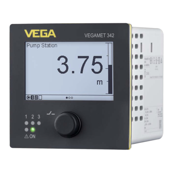
Principle of operation Application area The controller VEGAMET 342 feeds the connected 4 … 20 mA sen- sors, processes the measured values and displays them. The built-in housing is ideal for mounting in the switching cabinet. A large display... -
Page 9: Adjustment
PACTware/DTM or the VEGA Tools app is recom- mended. An overview of the available applications and functions as well as their adjustment options can be found in the appendix. -
Page 10: Packaging, Transport And Storage
Protected against solar radiation • Avoiding mechanical shock and vibration • Storage and transport Storage and transport temperature see chapter " Supplement - temperature Technical data - Ambient conditions" • Relative moisture 20 … 85 % VEGAMET 342 • 4 … 20 mA... -
Page 11: Mounting
The required cut-out is 92 x 92 mm (3.63 x 3.63 in) according to IEC 61554. A VEGAMET 342 in Ex version is an auxiliary, intrinsically safe instru- ment and may not be installed in explosion-endangered areas. -
Page 12: Connecting To Power Supply
The VEGAMET 342 can also be looped into the existing circuit like a normal ammeter. Note: With a VEGAMET 342 in Ex version, the passive input is not available. Connecting Connection technology The power supply and the inputs and outputs are connected via removable screw terminals. You can find information on the max. wire... -
Page 13: Wiring Plan
Power supply for four-wire sensors 2 mm sockets for connection of a VEGACONNECT/HART handheld Passive input 1 not available for Ex version Passive input 2 not available for Ex version Passive input not available for Ex version VEGAMET 342 • 4 … 20 mA... -
Page 14: Switch-On Phase
Output signals are set to failure, background lighting of the display lights red The current measured values are then displayed and transmitted to the outputs. The background lighting of the display changes to white. Passive input not available for Ex version VEGAMET 342 • 4 … 20 mA... -
Page 15: Access Protection
However, unlike the Bluetooth access code, it must be re-entered for each unlock. When using the adjustment app or DTM, the stored device code is then suggested to the user for unlocking. VEGAMET 342 • 4 … 20 mA... -
Page 16: Storing The Codes In Myvega
" PINs and Codes". This greatly simplifies the use of additional adjust- ment tools, as all Bluetooth access and device codes are automati- cally synchronized when connected to the " myVEGA" account VEGAMET 342 • 4 … 20 mA... -
Page 17: Set Up With The Integrated Display And Adjustment Unit
2 mm for direct connection of a VEGACONNECT or other HART modems. The adjustment of the con- nected sensor is carried out via the VEGA Tools app or via PACTware and appropriate DTM. VEGAMET 342 • 4 … 20 mA... -
Page 18: Measured Value And Menu Item Display
Bargraph measured value Active measured value indication The display is equipped with a background lighting for better visibility. Status display/back- ground lighting It serves simultaneously as a status display which is also visible from VEGAMET 342 • 4 … 20 mA... -
Page 19: Menu Overview
Damping Time setting for damping Linearisation Linearization settings Adjustment Adjustment settings Scaling Scaling settings Outputs Relay/current output settings Indication Description Basic settings Number of measured Number of displayed measured value indications value indications VEGAMET 342 • 4 … 20 mA... -
Page 20: Setup Steps
Information: When using PACTware and the respective DTM or the VEGA Tools app, additional settings can be carried out which are not possible or only partly possible with the integrated display and adjustment unit. - Page 21 Diagnosis Includes information on device type/status, … 7.4.1 Measurement loop The VEGAMET 342 is designed for the connection of two independ- ent sensors. Thus two independent measurements can be carried out. Furthermore, a third measuring point can be used to calculate a new value between the two input values.
- Page 22 When using the display and adjustment unit, the adjustment unit is always " mA". When using PACTware/DTM or the VEGA Tools app, further units can be selected. If these have been activated, they are also shown in the display.
- Page 23 In the menu item " Display - Options - Brightness" the brightness of the background lighting can be adjusted. Options - Contrast In the menu item " Display - Options - Contrast" the contrast of the display can be adjusted. VEGAMET 342 • 4 … 20 mA...
- Page 24 With activated protection of the parameter adjustment, the individual menu items can be selected and displayed, however the parameters can no longer be modified. Releasing the device adjustment is also possible in any menu item by entering the device code. VEGAMET 342 • 4 … 20 mA...
- Page 25 The simulation is automatically terminated after approx. 60 minutes. Device-TAG You can assign an unambiguous name to VEGAMET 342 to the Device-TAG via DTM/VEGA Tools app. This function is recommended when several instruments are implemented and a good documenta- tion of larger systems is required.
-
Page 26: Setup With Smartphone/Tablet (Bluetooth)
• Operating system: Android 5.1 or newer • Bluetooth 4.0 LE or newer Download the VEGA Tools app from the " Apple App Store", " Goog- le Play Store" or " Baidu Store" to your smartphone or tablet. Connecting Connecting Start the VEGA Tools app and select the function "... -
Page 27: Parameter Adjustment
The selected menu item, recognisable by the colour change, is dis- played in the right half. Fig. 11: Example of an app view - Setup adjustment Enter the requested parameters and confirm via the keyboard or the editing field. The settings are then active in the device. Close the app to terminate connection. VEGAMET 342 • 4 … 20 mA... -
Page 28: Setup With Pc/Notebook (Bluetooth)
Enter Bluetooth access For authentication, enter in the next menu window the 6-digit code Bluetooth access code: You can find the code on the information sheet " PINs and Codes" in the device packaging: VEGAMET 342 • 4 … 20 mA... -
Page 29: Parameter Adjustment
DTMs are compiled in a DTM Collec- tion. The DTMs can also be integrated into other frame applications according to FDT standard. Fig. 12: Example of a DTM view - Adjustment VEGAMET 342 • 4 … 20 mA... -
Page 30: Applications And Functions
10 Applications and functions The controller contains already preset applications and functions, which can be easily adjusted by means of an application assistant via PACTware/DTM or the VEGA Tools app. The following applications/ functions are described here as examples. •... - Page 31 Enter the measured value and unit (e.g. volume and m³) and the cor- responding scaling values for 100 % and 0 % (e.g. 100 m³, 0 m³). Configure relay First select the requested mode for the relay (" Overfill protection, dry run protection, switching window ON/OFF"). Also define the appro- VEGAMET 342 • 4 … 20 mA...
- Page 32 OFF. The switching points are set as follows: • Relay 1: Switch-off point 90 %, switch-on point 85 % • Relay 2: Switch-off point 5 %, switch-on point 10 % Information: The switch-on and switch-off point of the relays must not be set to the same switching point because this would cause a continuous switch- ing on and off when this threshold is reached. To avoid this effect also with fluctuating medium surfaces, it is a good idea to set a difference (hysteresis) of 5 % between the switching points. VEGAMET 342 • 4 … 20 mA...
-
Page 33: Pump Station With Pump Control Function
Symbol, activated pump control Relay 1 and 2 are assigned to the pump control Relay 3 is assigned to the pump control and signals failure Relay is free i.e. not assigned to the pump control VEGAMET 342 • 4 … 20 mA... - Page 34 This measure achieves an even utilization of the pumps and increases operational reliability. VEGAMET 342 • 4 … 20 mA...
- Page 35 Pump control 2/4 with dry weather pump is used to protect e.g. Option Dry weather pump rain retention basins with different sized pumps against overfilling. Normally (in fair weather), a pump with low capacity (dry weather pump) is sufficient to maintain the level in the retention basin at a safe level (Hi-Level). If heavy rainfall causes an increased inflow, the fair weather pump can no longer maintain the level. In such cases, a VEGAMET 342 • 4 … 20 mA...
- Page 36 Which pump is switched on depends on the selected pump mode. If all pumps are already switched on, the pump remains switched on. Note: If the pump is already switched on when the forced switchover is activated, the timer is not started. Only after the pump is switched off VEGAMET 342 • 4 … 20 mA...
- Page 37 Select in the DTM navigation section the menu items " Meas. loop - Outputs - Relay". • Relay 1 upper switching point = 60.0 % • Relay 1 lower switching point = 10.0 % VEGAMET 342 • 4 … 20 mA...
- Page 38 HiHi level is exceeded and the dry weather pump is switched off. The large pump then remains in operation until the switch-off point is reached. If the level rises again, the dry weather pump switches back on first. There is also the possibility of using multiple large pumps in alternat- ing mode. The algorithm for the switching function is then determined by the pump control mode. VEGAMET 342 • 4 … 20 mA...
- Page 39 Since in this case all pumps operate alternately in the same area, their switch-on and switch-off points must be the same. In addition, the mode " Alternating pump operation" must be active. VEGAMET 342 • 4 … 20 mA...
-
Page 40: Screen Control
Further application options are available on the corre- sponding DTM/app pages. A more detailed description of all available application options is included in the DTM online help. The following steps must be carried out in the application wizard: VEGAMET 342 • 4 … 20 mA... -
Page 41: Flow Measurement Flume/Weir
This constriction creates a certain backwater depending on the flow rate. The flow rate can now be derived from the level of this backwater. The current flow rate is shown on the display in the selected unit of measurement (e.g. m /h). In addition, the flow rate is made available via the current output and can thus be further processed by down- stream devices. VEGAMET 342 • 4 … 20 mA... - Page 42 Flow formula If the flow formula of your flume is known, you should select this op- tion, as the accuracy of the flow measurement is highest here. • Flow formula: Q = k x h Manufacturer definition If you use a Parshall flume from the manufacturer ISCO, this option must be selected. This gives you a high accuracy of flow measure- ment with easy configuration. Alternatively, you can also take over Q/h table values provided by the manufacturer here. • ISCO Parshall flume • Q/h table (assignment of height with corresponding flow in a table) VEGAMET 342 • 4 … 20 mA...
- Page 43 An application wizard guides you through the most common selection possibilities. Further application options are available on the corre- sponding DTM/app pages. A more detailed description of all available application options is included in the DTM online help. VEGAMET 342 • 4 … 20 mA...
- Page 44 • via the DTM/VEGA Tools app • time controlled (daily at any time) Configure measured value indication In the last step you can configure which and how many measured values are to be shown on the display. In addition, you can define the base of the display value, the display format and the optional bar graph. VEGAMET 342 • 4 … 20 mA...
-
Page 45: Diagnostics And Servicing
• Evaluation of fault messages • Checking the input/output signal A smartphone/tablet with the VEGA Tools app or a PC/notebook with the software PACTware and the suitable DTM offer you further com- prehensive diagnostic possibilities. In many cases, the causes can be determined in this way and the faults eliminated. - Page 46 Send instrument for repair F036 No executable Carry out another software update program Send instrument for repair No operable software Software update failed F037 RAM defective Switch the instrument off and on Carry out a reset Send instrument for repair VEGAMET 342 • 4 … 20 mA...
- Page 47 All relays which are assigned to the that are not con- pump control must be set to the same Pump control: figured with the mode Operating mode same mode are faulty assigned to the pump control VEGAMET 342 • 4 … 20 mA...
-
Page 48: Software Update
• Attach the completed form and, if need be, also a safety data sheet outside on the packaging • Ask the agency serving you to get the address for the return ship- ment. You can find the agency on our homepage. VEGAMET 342 • 4 … 20 mA... -
Page 49: Dismount
If personal data is stored on the old device to be disposed of, delete it before disposal. If you have no way to dispose of the old instrument properly, please contact us concerning return and disposal. VEGAMET 342 • 4 … 20 mA... -
Page 50: Certificates And Approvals
DIN EN ISO 14001. Help us to meet these requirements and observe the environmental instructions in the chapters " Packaging, transport and storage", " Disposal" of this operating instructions. VEGAMET 342 • 4 … 20 mA... -
Page 51: Supplement
≤ 3.6 mA Detection shortcircuit ≥ 21 mA Adjustment range 4 … 20 mA sensor Ʋ Empty adjustment 2.4 … 21.6 mA Ʋ Full adjustment 2.4 … 21.6 mA Temperature error relating to 20 mA 0.008 %/K VEGAMET 342 • 4 … 20 mA... - Page 52 If inductive loads or stronger currents are switched through, the gold plating on the relay contact surface will be permanently damaged. The contact is then no longer suitable for switching low-level signal circuits. Depending on the local conditions VEGAMET 342 • 4 … 20 mA...
- Page 53 Mechanical environmental conditions Vibrations (oscillations) Class 4M4 acc. to IEC 60721-3-4 (1 g, 4 … 200 Hz) Impacts (mechanical shock) Class 6M4 acc. to IEC 60721-3-6 (10 g/11 ms, 30 g/6 ms, 50 g/2.3 ms) VEGAMET 342 • 4 … 20 mA...
-
Page 54: Overview Applications/Functionality
Pressurized vessel • • Additional application examples VEGAMET Adjustment DTM/ Level measurement • • • Gauge measurement • • • Process pressure measurement • • • OP: Operating Panel (integrated display and adjustment unit) VEGAMET 342 • 4 … 20 mA... - Page 55 • Relay mode - Pump control 1 (same running time) • • • Relay mode - Pump control 2 (same running time) • • • Relay mode - Pump control 3 (fixed sequence) • • • Relay mode - Pump control 4 (fixed sequence) • • • VEGAMET 342 • 4 … 20 mA...
-
Page 56: Dimensions
Bluetooth access code • • • • Activate/deactivate Bluetooth communication • • • 14.3 Dimensions 111 mm 135 mm (4.37") (5.31") 15,8 mm 96 mm 118 mm (0.62") (3.78") (4.64") Fig. 23: Dimensions VEGAMET 342 VEGAMET 342 • 4 … 20 mA... -
Page 57: Industrial Property Rights
Les lignes de produits VEGA sont globalement protégées par des droits de propriété intellec- tuelle. Pour plus d'informations, on pourra se référer au site www.vega.com. VEGA lineas de productos están protegidas por los derechos en el campo de la propiedad indus- trial. Para mayor información revise la pagina web www.vega.com. - Page 58 Functional principle 9 Relay output 22 – Fail safe relay 23, 45 Repair 48 HART communication 17 Reset 25 HART resistance 17 Horizontal cylindrical tank 21 Scaling 22, 30 Hysteresis 32 Screen control 40 VEGAMET 342 • 4 … 20 mA...
- Page 59 Service hotline 45 Short-circuit 46 Simulation 25 Spherical tank 21 Storage tank 30 Switching window 23 Tendency 23 Trapezoidal weir 42 Triangular overfall 42 Type label 8 VEGA Tools app 17 Venturi flume 42 V-Notch 42 VEGAMET 342 • 4 … 20 mA...
- Page 60 Notes VEGAMET 342 • 4 … 20 mA...
- Page 61 Notes VEGAMET 342 • 4 … 20 mA...
- Page 62 Notes VEGAMET 342 • 4 … 20 mA...
- Page 63 Notes VEGAMET 342 • 4 … 20 mA...
- Page 64 Subject to change without prior notice © VEGA Grieshaber KG, Schiltach/Germany 2022 VEGA Grieshaber KG Am Hohenstein 113 Phone +49 7836 50-0 77761 Schiltach E-mail: info.de@vega.com...
Need help?
Do you have a question about the VEGAMET 342 and is the answer not in the manual?
Questions and answers