Advertisement
Quick Links
Advertisement

Related Manuals for Vega 20Y


Summary of Contents for Vega 20Y
- Page 1 CONTROL EQUIPMENT 20Y INTELLIGENT WATER PUMP CONTROLLER 2024 V1 24-01...
-
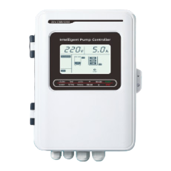
Page 2: Pump Controller
The 20Y 1-phase LCD display pump controller for single pump is designed with built-in start capacitor, facilitates the startup of deep well submersible pumps, and protects them from abnormalities, keeping the well pumping system up and running. - Page 3 Main Function Pressure Control Options: Choose between a two-wire pressure switch or a three-wire electric contact pressure gauge, providing versatile options to suit your specific pressure control needs. Liquid Level Control Options: Opt for either electrode probe or float switch detection for versatile and effective liquid level control.
- Page 4 Inner Compoments LCD Screen MAIN KEY Overload current setting, Continuous press 3 times to FAULT Key increase QUERY check the latest 10 failures OVERLOAD NO-load current setting Time setting key, NO LOAD TIME SETTING Key decrease protection setting selection Start or stop pump in manual, START AUTO / Manual Key AUTO...
- Page 5 Installation Guide 1. Host Installation: Mount the controller securely on the wall. Open the wiring box and connect the power lines, pump lines, pressure control lines, or probes following the wiring diagram. 2. Signal Line Connection: Ensure that no two probe lines are short-circuited. Avoid contact with the pool wall, stay away from areas with strong interference or electrical appliances, and keep the signal lines separate from power supply lines.
- Page 6 Key settings and functions MAIN KEY Overload current setting, Continuous press 3 times to FAULT Key increase QUERY check the latest 10 failures OVERLOAD NO-load current setting Time setting key, NO LOAD TIME SETTING Key decrease protection setting selection Start or stop pump in manual, START AUTO / Manual Key AUTO...
- Page 7 A. Time Setting ‘ON’: After setting the ON time, the controller will automatically switch on the pump according to the set time. The time setting is in hours and operates in a cyclic starting mode. Press the key for 3 seconds and release it upon a beep sound. Upon entering the time setting TIME SETTING mode, “P03”...
- Page 8 3. AUTO/Manual Mode (to switch by pressing the key) AUTO MANUAL A. Under AUTO: In this mode, all functions of the pump controller, such as water supply, drainage, constant water supply, and time setting ON, operate fully automatically. B. Under Manual: In this mode, the pump controller is not controlled by water level or pressure; it is only controlled by pressing the key.
- Page 9 5. No-Load Protection NO LOAD When the working current of the water pump falls below the set no-load current, the pump automatically stops. No-load protection follows an inverse time limit principle: the lower the current compared to the set value, the faster the no-load protection will activate. No—load protection current setting: This function helps control and protect the water pump in cases of water shortage, dry runs, or impeller damage.
-
Page 10: Installation & Wiring
Installation Wiring Water Supply Probe ATTENTION a. Position the probes at the High, Middle, and Low levels, then connect it to terminals 1, 2, and 3. b. Low Water Level — START, High Water Level — STOP. www.vegapumps.co.za... - Page 11 Drainage Probe ATTENTION a. Place the probes at the High, Middle, and Low positions, then connect to terminals 4, 5, and 6. b. High Water Level — START, Low Water Level — STOP. www.vegapumps.co.za...
- Page 12 Drainage Float Switch ATTENTION a. Connect the float wires to terminals 4 and 5 (Red wire to terminal 4, Black wire to terminal 5). b. When the float is up, the pump starts. When the float is down, the pump stops. www.vegapumps.co.za...
- Page 13 Water Supply Float Switch ATTENTION a. Connect the float wires to terminals 1 and 2 (Red wire to terminal 1, Black wire to terminal 2). b. When the float is down, the pump starts. When the float is up, the pump stops. www.vegapumps.co.za...
- Page 14 Water Supply - Electric Contact Pressure Gauge ATTENTION a. Connect the pressure gauge wire to the terminal 1, 2 and 3. b. Indicator “Middle” - gauge not connected or wrong connection. c. Indicator “High” - exchange the terminal wire 1 with 3. d.
- Page 15 Water Supply - Pressure Switch ATTENTION a. If the pressure switch is set to disconnect, the pump will stop. Connect the input and output wires of the pressure switch to terminals 4 and 5. b. If the pressure switch is set to disconnect, the pump will start. Connect the input and output wires of the pressure switch to terminals 1 and 2.
- Page 16 Water Supply - Upper & Lower Tank ATTENTION a. Position the probe at the High, Middle, and Low levels. Connect the upper tank probe to terminals 1, 2, and 4, and the lower tank probe to terminals 4, 5, and 6. b.
-
Page 17: Troubleshooting
Trouble Shooting Fault Possible Cause Solutions Pump stops after starting (No-Load 1. Water shortage 1. Check water supply. light ON) 2. Impeller damage 2. Inspect the water pump. 3. Water shortage current parameter 3. Set the water shortage current set too high relative to pump’s lower than the pump’s operating operating current.
Need help?
Do you have a question about the 20Y and is the answer not in the manual?
Questions and answers