Table of Contents

Related Manuals for Apogee 2349 DLTM4


Summary of Contents for Apogee 2349 DLTM4
- Page 1 AL6300 DATA LINK TEST SET PRODUCT MODEL 2349 DLTM4 LINE INSTRUCTIONS MODEL 2349 DLTM4 DATA LINK TEST MODULE 210 South 3 Street, North Wales, PA 19454 POGEE Tel: 215.699.2060 Fax: 215.699.2061 09.21.2017...
- Page 2 This page left intentionally blank...
-
Page 3: Table Of Contents
AL6300 DATA LINK TEST SET PRODUCT LINE MODEL 2349 DLTM4 TABLE OF CONTENTS FEATURES ..........................1 PURPOSE OF MODULE ......................1 FUNCTIONAL DESCRIPTION ....................1 SPECIFICATION ......................... 2 INSTALLATION ......................... 3 GENERAL ..........................3 MODULE PLACEMENT CONSIDERATIONS ..............3 5.2.1 SYNC STATUS INDICATION (AL6300-LCD CHASSIS SYNC DISPLAY) .. - Page 4 210 South 3 Street, North Wales, PA 19454 POGEE Tel: 215.699.2060 Fax: 215.699.2061 10.31.2012...
- Page 5 AL6300 DATA LINK TEST SET PRODUCT LINE MODEL 2349 DLTM4 TABLE OF FIGURES Figure 1: Model 2349 DLTM4 Block Diagram ........................2 Figure 2: Model 2349 Connection Panel and Side Views ....................4 Figure 3: TTL Data, Clock and System Time (ST) Input ....................6 Figure 4: RS-422 Data and Clock Input ..........................
-
Page 7: Features
User Configurable Measurements 2. PURPOSE OF MODULE The Model 2349 DLTM4 provides the capabilities needed to perform bit-error-rate performance testing of data links and associated hardware, such as PCM bit synchronizers and frame synchronizers. Data bit rates from 100 bps to 50 Mbps are supported. Measurement capabilities include: Bit Error related tests, bit slip tests, and measurement of round trip data link delay. -
Page 8: Specification
General and Unique Data Apogee Labs Inc. products are sold by description only. Apogee Labs Inc. reserves the right to make changes in circuit design, software, hardware and/or specifications at any time without notice. Although Apogee Labs Inc. believes that the information provided is current and accurate, Apogee Labs Inc. does not assume any responsibility or liability for the use of any product described. -
Page 9: Installation
The DLTM4 module is the test data generator / receiver and measurement device used in the AL6300-LCD Data Link Test Set. It also may be used in the AL4300-LCD series equipment in combination with Apogee Labs data multiplexing / demultiplexing devices. The module is self-contained: transmitter, receiver, and measurement functions are combined with a microprocessor that supports front panel and remote control operations. -
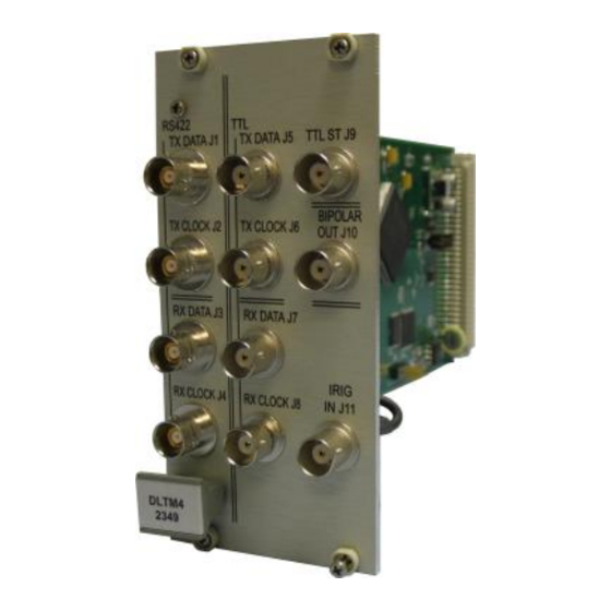
Page 10: Figure 2: Model 2349 Connection Panel And Side Views
JP3 JP4 Figure 2: Model 2349 Connection Panel and Side Views The BNC input connections are terminated on the module. Jumpers are installed or removed to select the desired value of shunt resistance. Table 1 defines the resulting shunt resistance for given jumper configurations. Figure 2 indicates the location of each jumper. -
Page 11: Table 2: I/O Connector Definitions
AL6300 DATA LINK TEST SET PRODUCT LINE MODEL 2349 DLTM4 Table 2: I/O Connector Definitions Reference Signal Name Standard Direction* TX DATA RS-422 RS422 TTL ST J9 TX DATA J1 TX DATA J5 TX CLOCK RS-422 RX DATA RS-422 BIPOLAR... -
Page 12: Operation
Output Circuits Input Circuits 5Ω TTL Driver TTL Receiver 24.9 24.9 Figure 5: TTL Data and Clock Output 24.9 Figure 3: TTL Data, Clock and System Time (ST) Input 422 Driver 1.5K 422 Receiver 49.8 Figure 6: RS-422 Data and Clock Output 1.5K Figure 4: RS-422 Data and Clock Input Bipolar Driver... -
Page 13: Measurements Menu
AL6300 DATA LINK TEST SET PRODUCT LINE MODEL 2349 DLTM4 5.4.1 MEASUREMENTS MENU The initial screen that the DLTM4 comes to is the Measurements Menu. The Measurements menu is depicted in Figure 8. Figure 8: Measurements Menu The Measurements Display provides status of the currently running test. The Clear (F5) button clears out any current measurements and allows the test to continue running. -
Page 14: Output Settings
5.4.2 OUTPUT SETTINGS Selecting the Output Settings screen brings the display shown in Figure 9. Figure 9: TX SETUP SCREEN Using this menu, configure the primary functions of the Transmit (output) interface. Each of the fields contained on the display are explained below. The Output settings control the data and clock characteristics, including data content, Doppler shifting, error insertion and blanking. - Page 15 AL6300 DATA LINK TEST SET PRODUCT LINE MODEL 2349 DLTM4 Blanking Blanking Enable or Disable Non-Blank Define the number of bits transmitted that remain as intended by the generator before permitting the blanking function to force bits to zero. This value is programmable from 64 to 1024.
-
Page 16: Figure 10: Clock Polarity Settings
DIGITAL VALUE POS CLOCK TTL NEG CLOCK TTL POS CLOCK RS-422 signals: A(+) red, B(-) blue NEG CLOCK RS-422 signals: A(+) red, B(-) blue Figure 10: CLOCK POLARITY SETTINGS DIGITAL VALUE POS TTL DATA NEG TTL DATA POS DATA RS-422 signals: A(+) red,... -
Page 17: Input Settings
AL6300 DATA LINK TEST SET PRODUCT LINE MODEL 2349 DLTM4 5.4.3 INPUT SETTINGS The Input Settings display provides the ability to control the parameters associated with the data and clock being received by the DLTM4. This screen is shown in Figure 12. -
Page 18: Prn Settings
5.4.5 PRN SETTINGS The PRN SETUP screen is used to define the pseudo random number sequence and its generator direction. The information on this screen is only pertinent if, on the Output SETUP screen in Figure 9, the TYPE is set to PRN. Figure 13: PRN Generator Setup Screen The following table describes the fields from the PRN Setting display. -
Page 19: Pcm Settings
AL6300 DATA LINK TEST SET PRODUCT LINE MODEL 2349 DLTM4 5.4.6 PCM SETTINGS The DLTM4 is programmable to output either a PRN data sequence or a simulated time-division-multiplexed (TDM) PCM data stream. The PCM Settings display is used to configure the fixed parameters of the TDM stream. Dynamic data associated with the stream are configured in this menu and in the EDIT PCM menu (Figure 15). -
Page 20: Edit Pcm
5.4.7 EDIT PCM The EDIT PCM menu permits the definition of the TDM output data stream. Up to 4096 data words per frame may be generated using a combination of instructions defined in Table 8. Figure 15: PCM DATA EDIT SCREEN Up to 32 instructions are accepted for this process. -
Page 21: Data Log Setup
AL6300 DATA LINK TEST SET PRODUCT LINE MODEL 2349 DLTM4 5.4.8 DATA LOG SETUP Automatic logging of test data results is supported by the DLTM4. The Data Log Setup display in Figure 16 permits the user to configure this automatic feature. -
Page 22: Presets
5.4.9 PRESETS The Presets display allows the saving and recalling of configurations to and from memory. The display is shown below. Figure 17: PRESET Control Screen The PRESET menu is used to define a Preset file number nn, in the range from 1 to 30, to which the current module program is to be stored or from which the module is to be loaded. -
Page 23: 5.4.10 Data Capture
AL6300 DATA LINK TEST SET PRODUCT LINE MODEL 2349 DLTM4 5.4.10 DATA CAPTURE The Data Capture display provides the facility to capture and display up to four selected words that are being received from the incoming TDM PCM data stream. Figure 18 shows what this display looks like. -
Page 24: Remote Commands
REMOTE COMMANDS 5.5.1 SET is used to assign values to program registers. The SET command has two fields separated by a comma: the register and the operand. The register is the desired programming field to be programmed. Refer to the DLTM programming pages for the allowable register names and values for each field. - Page 25 AL6300 DATA LINK TEST SET PRODUCT LINE MODEL 2349 DLTM4 Table 12: Total Instruction Set Field Returned Value / Comments Found in Sub-Menu TEST LINK DELAY Initiates the link delay test and places the result into the LINK DLY field Figure 8 for display.
- Page 26 Table 12: Total Instruction Set Field Returned Value / Comments Found in Sub-Menu RX CODE NRZ-L, NRZ-M, NRZ-S, BiP-L, BiP-M, BiP-S, Figure 12 RNRZ-15, DM-M, DM-S START 100 to 50000000 / measured in bits per second Figure 9 100 to 50000000 / measured in bits per second Figure 9 1 –...
-
Page 27: Application Notes
AL6300 DATA LINK TEST SET PRODUCT LINE MODEL 2349 DLTM4 Table 12: Total Instruction Set Field Returned Value / Comments Found in Sub-Menu PV## The PCM Value field sets the value that is to be set or read into/from the Figure 15 value defined in the PC## field. -
Page 28: Blanking
6.1.2.2 Insert Known Error Rate This feature is useful when testing the DLTM4 receiver and display or for testing the error recovery 6.1.3 BLANKING The Blanking feature forces a program-selectable number of data bits to the zero state after bit coding is applied. This simulates line dropouts and provides a measure of the ability of a bit synchronizer to achieve or maintain Lock during and after data periods without transitions. -
Page 29: Generating Pcm Data Streams
AL6300 DATA LINK TEST SET PRODUCT LINE MODEL 2349 DLTM4 GENERATING PCM DATA STREAMS PRN GENERATOR ERROR INSERT, LOCAL CODE CONVERT, TO TX OUTPUT POLARITY BIT CLOCK INTERFACES SELECT EXTERNAL (ST) PCM FRAME GENERATOR WORD, PARALLEL FRAME DATA MARKS PCM DATA GENERATOR... -
Page 30: Examples Of Tdm Pcm Formats
6.2.1.3 SETUP THE FRAME COUNTER: The Frame Count commands (Figure 14) are used to configure the Frame Counter and are part of the PCM SETUP menu (Figure 14). The Frame Counter is a binary counter that increments or decrements by one count in each frame. 5.4.10 EXAMPLES OF TDM PCM FORMATS 6.2.2.1 EXAMPLE #1... -
Page 31: Measuring Link Delay On A Full Duplex Link
AL6300 DATA LINK TEST SET PRODUCT LINE MODEL 2349 DLTM4 Bits per Word = 16; use the largest number of hits per frame Words per Frame = 4096; use the largest number of words per frame MSB / LSB first = MSB;... -
Page 32: Setup & Configuration
The DLTM4 provides the facility for a user to measure the time delay introduced by a data path. This provides an easy solution for determining the path delay of a data communication system, such as through a satellite path. Link delay is measured directly on the DLTM4 (Model 2349). The DLTM4 is configured to run PRN data through the system with the data being looped back to the DLTM4. - Page 33 AL6300 DATA LINK TEST SET PRODUCT LINE MODEL 2349 DLTM4 Setup the transmit and receive interfaces and data coding to be compatible with the data link connections. Turn-off Blanking and Error generation. Configure the Doppler menu (Figure 9) as follows: ...
Need help?
Do you have a question about the 2349 DLTM4 and is the answer not in the manual?
Questions and answers