Table of Contents
Advertisement
Quick Links
Advertisement
Table of Contents

Related Manuals for Apogee SI Series


Summary of Contents for Apogee SI Series
-
Page 1: Owner's Manual
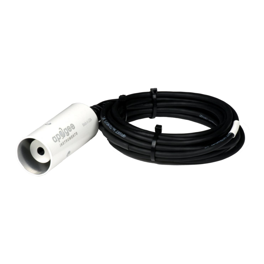
OWNER’S MANUAL RESEARCH-GRADE INFRARED RADIOMETER Models SI-511, SI-521, SI-531, and SI-5H1 Rev: 10-Dec-2020 APOGEE INSTRUMENTS, INC. | 721 WEST 1800 NORTH, LOGAN, UTAH 84321, USA TEL: (435) 792-4700 | FAX: (435) 787-8268 | WEB: APOGEEINSTRUMENTS.COM Copyright © 2020 Apogee Instruments, Inc. -
Page 2: Table Of Contents
TABLE OF CONTENTS Owner’s Manual ....................................1 Declaration of Conformity ............................... 3 Introduction ..................................... 4 Sensor Models ..................................5 Specifications ................................... 6 Deployment and Installation ..............................7 Cable Connectors ..................................9 Operation and Measurement ..............................10 Maintenance and Recalibration ............................. 18 Troubleshooting and Customer Support .......................... -
Page 3: Declaration Of Conformity
RoHS 3 compliant using exemption 6c. Further note that Apogee Instruments does not specifically run any analysis on our raw materials or end products for the presence of these substances, but rely on the information provided to us by our material suppliers. -
Page 4: Introduction
(soil, vegetation, water, snow) temperature measurement in energy balance studies. Apogee Instruments SI series research-grade infrared radiometers consist of a thermopile detector, germanium filter, precision thermistor (for detector reference temperature measurement), and signal processing circuitry mounted in an anodized aluminum housing, and a cable to connect the sensor to a measurement device. -
Page 5: Sensor Models
If you need the manufacturing date of your sensor, please contact Apogee Instruments with the serial number of your sensor. The four FOV options and associated model numbers are shown below:... -
Page 6: Specifications
(316), M8 connector located 25 cm from sensor head Calibration Traceability Apogee SI series infrared radiometers are calibrated to the temperature of a custom blackbody cone held at multiple fixed temperatures over a range of radiometer (detector/sensor body) temperatures. The temperature of the blackbody cone is measured with replicate precision thermistors thermally bonded to the cone surface. -
Page 7: Deployment And Installation
An Apogee Instruments model AM-220 mounting bracket is recommended for mounting the sensor to a cross arm or pole. The AM-220 allows adjustment of the angle of the sensor with respect to the target and accommodates... - Page 8 4.461 18.865 Narrow SI-5HR 16° 5° 0.403 1.15 3.341 Ultra-Narrow SI-531 14° 0.787 2.447 8.544 A simple FOV calculator for determining target dimensions based on infrared radiometer model, mounting height, and mounting angle, is available on the Apogee website: https://www.apogeeinstruments.com/irr-calculators.
-
Page 9: Cable Connectors
CABLE CONNECTORS Apogee sensors offer cable connectors to simplify the process of removing sensors from weather stations for calibration (the entire cable does not have to be removed from the station and shipped with the sensor). The ruggedized M8 connectors are rated IP68, made... -
Page 10: Operation And Measurement
OPERATION AND MEASUREMENT All SI-500 series radiometers have a Modbus output, where target and detector temperatures are returned in digital format. Measurement of SI-500 series radiometers requires a measurement device with a Modbus interface that supports the Read Holding Registers (0x03) function. Wiring White: RS-232 RX / RS-485 Positive Blue: RS-232 TX / RS-485 Negative... - Page 11 Sensor Calibration Apogee SI series infrared radiometers are calibrated in a temperature controlled chamber that houses a custom- built blackbody cone (target) for the radiation source. During calibration, infrared radiometers (detectors) are held in a fixture at the opening of the blackbody cone, but are thermally insulated from the cone. Detector and target temperature are controlled independently.
- Page 12 Sensor addresses Each sensor is given an address from 1 to 247. Apogee sensors are shipped with a default address of 1. If using multiple sensors on the same Modbus line, the sensor’s address will have to be changed by writing the Slave Address register.
- Page 13 Communication Parameters: Apogee Sensors communicate using the Modbus RTU variant of the Modbus protocol. The default communication parameters are as follows: Slave address: 1 Baudrate: 19200 Data bits: 8 Stop bits: 1 Parity: Even Byte Order: Big-Endian (most significant byte sent first) The baudrate and slave address are user configurable.
- Page 14 (0 = none, 1 = odd, 2 = even) number of stopbits running average *Registers marked with an asterisk (*) cannot be written to unless a specific procedure is followed. Contact Apogee Instruments to receive the procedure for writing these registers...
- Page 15 Target temperature is output directly in digital format. The detector output from SI series radiometers follows the fundamental physics of the Stefan-Boltzmann Law, where radiation transfer is proportional to the fourth power of absolute temperature. A modified form of the Stefan-Boltzmann equation is used to calibrate sensors, and subsequently, calculate target temperature: ...
- Page 16 where T is target temperature [K], T is detector temperature [K], S is the millivolt signal from the detector, m is slope, and b is intercept. The mV signal from the detector is linearly proportional to the energy balance between the target and detector, analogous to energy emission being linearly proportional to the fourth power of temperature in the Stefan-Boltzmann Law.
- Page 17 Sensor Background where T [K] is temperature measured by the infrared radiometer (brightness temperature), T [K] is actual Sensor Target temperature of the target surface, T [K] is brightness temperature of the background (usually the sky), and Background σ...
-
Page 18: Maintenance And Recalibration
Blocking of the optical path between the target and detector, often due to moisture or debris on the filter, is a common cause of inaccurate measurements. The filter in SI series radiometers is inset in an aperture, but can become partially blocked in four ways: 1. -
Page 19: Troubleshooting And Customer Support
Compatible Measurement Devices (Dataloggers/Controllers/Meters) Any datalogger or meter with RS-232/RS-485 that can read/write float or integer values. An example datalogger program for Campbell Scientific dataloggers can be found on the Apogee webpage at http://www.apogeeinstruments.com/downloads/#datalogger. Cable Length All Apogee sensors use shielded cable to minimize electromagnetic interference. -
Page 20: Return And Warranty Policy
RETURN AND WARRANTY POLICY RETURN POLICY Apogee Instruments will accept returns within 30 days of purchase as long as the product is in new condition (to be determined by Apogee). Returns are subject to a 10 % restocking fee. WARRANTY POLICY... - Page 21 84321, USA 5. Upon receipt, Apogee Instruments will determine the cause of failure. If the product is found to be defective in terms of operation to the published specifications due to a failure of product materials or craftsmanship, Apogee Instruments will repair or replace the items free of charge.
Need help?
Do you have a question about the SI Series and is the answer not in the manual?
Questions and answers