Sign In
Upload
Manuals
Brands
Apogee Manuals
Measuring Instruments
2349 DLTM4
Apogee 2349 DLTM4 Manuals
Manuals and User Guides for Apogee 2349 DLTM4. We have
1
Apogee 2349 DLTM4 manual available for free PDF download: Instructions Manual
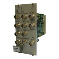
Apogee 2349 DLTM4 Instructions Manual (33 pages)
DATA LINK TEST MODULE
Brand:
Apogee
| Category:
Measuring Instruments
| Size: 1.26 MB
Table of Contents
Table of Contents
3
1 Features
7
2 Purpose of Module
7
3 Functional Description
7
4 Specification
8
Figure 1: Model 2349 DLTM4 Block Diagram
8
5 Installation
9
General
9
Module Placement Considerations
9
Sync Status Indication (Al6300-Lcd Chassis Sync Display)
9
Connection & Physical Configuration
9
Figure 2: Model 2349 Connection Panel and Side Views
10
Table 1: Jumper Configuration
10
Table 2: I/O Connector Definitions
11
Operation
12
Figure 3: TTL Data, Clock and System Time (ST) Input
12
Figure 4: RS-422 Data and Clock Input
12
Figure 5: TTL Data and Clock Output
12
Figure 6: RS-422 Data and Clock Output
12
Figure 7: Bipolar Output
12
Figure 8: Status Menu
13
Measurements MENU
13
Table 3: Selectable Definitions of the Actions Field on the Status Screen
13
Figure 9: TX SETUP SCREEN
14
Output SETTINGS
14
Table 4: Selectable Definitions of the Actions Field on the Status Screen
14
Figure 10: CLOCK POLARITY SETTINGS
16
Figure 11: DATA POLARITY SETTINGS
16
Figure 12: Receiver Setup Screen
17
Input SETTINGS
17
Table 5: Selectable Definitions of the Actions Field on the RX Settings Display
17
Figure 13: PRN Generator Setup Screen
18
Prn Settings
18
Table 6: Selectable Definitions of the Actions Field on the PRN Settings Display
18
Figure 14: PCM SETUP SCREEN
19
Pcm Settings
19
Table 7: Selectable Definitions of the Actions Field on the PCM Settings Display
19
Edit Pcm
20
Figure 15: PCM DATA EDIT SCREEN
20
Table 8: Selectable Definitions of the Actions Field on the EDIT PCM Display
20
Data Log Setup
21
Figure 16: Data Log Setup Display
21
Table 9: Selectable Definitions of the Actions Field on the Data Log Setup Display
21
Figure 17: PRESET Control Screen
22
Presets
22
Table 10: Selectable Definitions of the Actions Field on the Presets Display
22
5.4.10 Data Capture
23
Figure 18: DATA CAPTURE Screen
23
Table 11: Selectable Definitions of the Actions Field on the Presets Display
23
Remote Commands
24
Set
24
Read
24
Help
24
Save/Load
24
Command Definitions
24
Table 12: Total Instruction Set
24
6 Application Notes
27
Generalized Data Link Testing
27
I" & "Q" Channels
27
Error Simulations
27
Figure 19: Typical Telemetry Data Link Block Diagram
27
Blanking
28
Symmetry Tests
28
Pulse Coded Modulation
28
Generating Pcm Data Streams
29
Basics
29
Figure 20: DLTM Transmitter Block Diagram
29
Examples of Tdm Pcm Formats
30
Measuring Link Delay on a Full Duplex Link
31
Figure 21: Basic Setup for Measuring Link Delay
31
Measuring the Link Delay
32
Setup & Configuration
32
Doppler Shift with the Dltm4
32
Advertisement
Advertisement
Related Products
Apogee 21054010
Apogee Rosetta 200
Apogee Element 24
Apogee Thunderbolt 2
Apogee 2020 ETHCX1
Apogee 21065040
Apogee 11056017
Apogee MC-100
Apogee MI-210
Apogee MI-220
Apogee Categories
Accessories
Measuring Instruments
Media Converter
Speakers
Recording Equipment
More Apogee Manuals
Login
Sign In
OR
Sign in with Facebook
Sign in with Google
Upload manual
Upload from disk
Upload from URL