Table of Contents

Related Manuals for Apogee SI-411


Summary of Contents for Apogee SI-411
- Page 1 OWNER’S MANUAL INFRARED RADIOMETER Models SI-411, SI-421, SI-431, and SI-4H1 (including SS models) APOGEE INSTRUMENTS, INC. | 721 WEST 1800 NORTH, LOGAN, UTAH 84321, USA TEL: (435) 792-4700 | FAX: (435) 787-8268 | WEB: APOGEEINSTRUMENTS.COM...
- Page 2 TABLE OF CONTENTS...
-
Page 3: Declaration Of Conformity
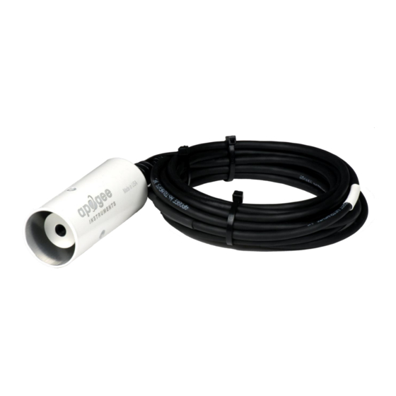
(PBB), polybrominated diphenyls (PBDE). Further note that Apogee Instruments does not specifically run any analysis on our raw materials or end products for the presence of these substances, but rely on the information provided to us by our material suppliers. - Page 4 Apogee Instruments SI series infrared radiometers consist of a thermopile detector, germanium filter, precision thermistor (for detector reference temperature measurement), and signal processing circuitry mounted in an anodized aluminum housing, and a cable to connect the sensor to a measurement device.
-
Page 5: Sensor Models
If you need the manufacturing date of your sensor, please contact Apogee Instruments with the serial number of your sensor. The four FOV options and associated model numbers are shown below:... -
Page 6: Specifications
Calibration Traceability Apogee SI series infrared radiometers are calibrated to the temperature of a custom blackbody cone held at multiple fixed temperatures over a range of radiometer (detector/sensor body) temperatures. The temperature of the blackbody cone is measured with replicate precision thermistors thermally bonded to the cone surface. -
Page 7: Deployment And Installation
An Apogee Instruments model AM-210 mounting bracket is recommended for mounting the sensor to a cross arm or pole. The AM-210 allows adjustment of the angle of the sensor with respect to the target and accommodates... - Page 8 Different mounting geometries (distance and angle combinations) produce different target shapes and areas, as shown below. A simple FOV calculator for determining target dimensions based on infrared radiometer model, mounting height, and mounting angle, is available on the Apogee website: http://www.apogeeinstruments.com/using-your-apogee- instruments-infrared-radiometer/.
-
Page 9: Cable Connectors
(pyranometer pictured) Instructions Pins and Wiring Colors: All Apogee connectors have six pins, but not all pins are used for every sensor. There may also be unused wire colors inside the cable. To simplify data logger connection, we remove the unused pigtail lead colors at the data logger end of the cable. -
Page 10: Operation And Measurement
M or C command. VERY IMPORTANT : Apogee changed all wiring colors of our bare-lead sensors in March 2018 in conjunction with the release of inline cable connectors on some sensors. To ensure proper connection to your data device, please note your serial number or if your sensor has a stainless-steel connector 30 cm from the sensor head then use the appropriate wiring configuration below. - Page 11 Sensor Calibration Apogee SI series infrared radiometers are calibrated in a temperature controlled chamber that houses a custom- built blackbody cone (target) for the radiation source. During calibration, infrared radiometers (detectors) are held in a fixture at the opening of the blackbody cone, but are thermally insulated from the cone. Detector and target temperature are controlled independently.
- Page 12 SDI-12 Interface The following is a brief explanation of the serial digital interface SDI-12 protocol instructions used in Apogee SI-400 series infrared radiometers. For questions on the implementation of this protocol, please refer to the official version of the SDI-12 protocol: http://www.sdi-12.org/specification.php...
- Page 13 where a is the sensor address (“0-9”, “A-Z”, “a-z”) and M is an upper-case ASCII character. The target temperature and sensor body temperature are separated by the sign “+” or “-“, as in the following example (0 is the address): Command Sensor Response Sensor Response when data is ready...
- Page 14 Command Response Description aAb! b<cr><lf> Change the address of the sensor where a is the current (old) sensor address (“0-9”, “A-Z”), A is an upper-case ASCII character denoting the instruction for changing the address, b is the new sensor address to be programmed (“0-9”, “A-Z”), and ! is the standard character to execute the command.
- Page 15 be found at http://www.nws.noaa.gov/oh/hrl/shef/indexshef.htm. The second value is the units of the parameter. Additional fields with more information are optional. The Measurement Parameter Commands work with the Verification Command (aV!), Measurement Commands (aM!, aM1! … aM9!, aMC!, aMC1! … aMC9!), and Concurrent Measurement Commands (aC!, aC1! … aC9! , aCC!, aCC1! …...
- Page 16 During the calibration process, m and b are determined at each detector temperature set point (10 C increments – T across a -15 C to 45 C range) by plotting measurements of T versus mV. The derived m and b coefficients are then plotted as function of T and second order polynomials are fitted to the results to produce equations that determine m and b at any T...
- Page 17 where T [K] is temperature measured by the infrared radiometer (brightness temperature), T [K] is actual Sensor Target temperature of the target surface, T [K] is brightness temperature of the background (usually the sky), and Background σ is the Stefan-Boltzmann constant (5.67 x 10 ).
-
Page 18: Maintenance And Recalibration
Use only gentle pressure when cleaning the filter with a cotton swab, to avoid scratching the outer surface. The solvent should be allowed to do the cleaning, not mechanical force. It is recommended that infrared radiometers be recalibrated every two years. See the Apogee webpage for details regarding return of sensors for recalibration (http://www.apogeeinstruments.com/tech-support-recalibration-... -
Page 19: Troubleshooting And Customer Support
SDI-12 protocol limits cable length to 60 meters. For multiple sensors connected to the same data line, the maximum is 600 meters of total cable (e.g., ten sensors with 60 meters of cable per sensor). See Apogee webpage for details on how to extend sensor cable length (http://www.apogeeinstruments.com/how-to-make-a-...
Need help?
Do you have a question about the SI-411 and is the answer not in the manual?
Questions and answers